Clamping table type connecting piece

A connector and desktop technology, which is applied in the field of card desktop connectors, can solve the problems of snap ring drop, fast and convenient connection, and inability to realize docking, etc., and achieve the effect of convenient connection and assembly

Inactive Publication Date: 2015-12-23
周兆弟
View PDF15 Cites 15 Cited by
  • Summary
  • Abstract
  • Description
  • Claims
  • Application Information

AI Technical Summary

Problems solved by technology

However, this solution needs to assemble the intermediate nut, elastic member, and snap ring at one time during assembly, and the assembly of the snap r

Method used


Image

  • Clamping table type connecting piece
  • Clamping table type connecting piece
  • Clamping table type connecting piece

Examples


Embodiment 1

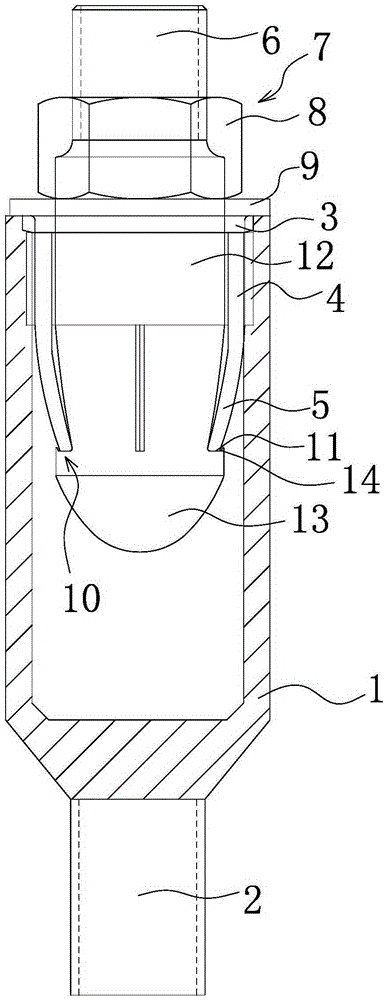
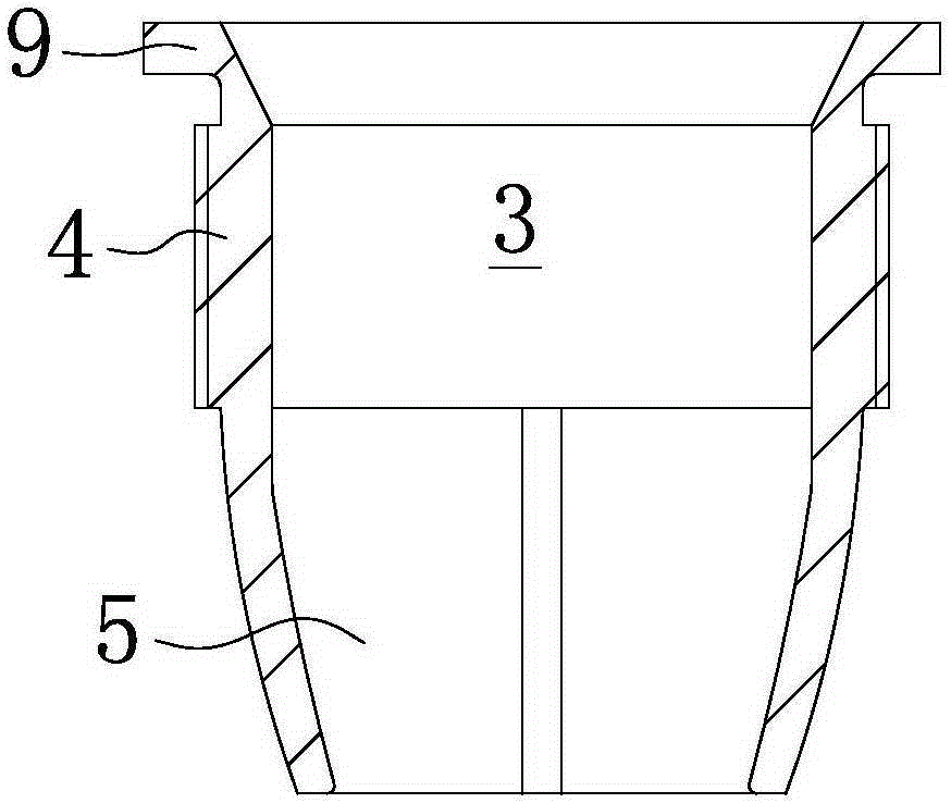
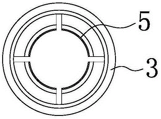
[0027] Such as figure 1 As shown, a card-type connector includes a connecting nut 1, the bottom of the connecting nut 1 has a strip-shaped connecting rod 2, and a screw sleeve 3 is screwed inside the connecting nut 1, and the screw sleeve 3 is screwed inside the connecting nut 1. One end of the sleeve 3 is a cylindrical screw sleeve connection end 4, and the other end is bifurcated to form several cards 5. There is a gap between every two adjacent cards 5, and the middle of the card 5 faces away from the axis of the screw sleeve 3. The protrusion makes the outer surface of the card 5 form an arc surface, making the card 5 elastic and easy to fold. The number of cards 5 can be more than 2, preferably 3 or more than 3, such as image 3 As shown, the number of cards is 4 pieces, such as Figure 4 As shown, the number of cards is 6 pieces. The threaded sleeve 3 has a passage for inserting the insert rod 6. When the insert rod 6 is inserted into the threaded sleeve 3, the insert...

Embodiment 2

[0039]The structure and working principle of this embodiment are basically the same as that of Embodiment 1, the difference is that, as Figure 7-8 As shown, the card table mechanism 10 includes an annular stepped portion 16 arranged on the inner wall of the connecting nut 1, the end of the card 5 protrudes outward to form a card bar 17, and the end of the insertion rod 6 has a The frustum-conical expansion strip 18, when the expansion strip 18 moves toward the mouth of the connecting nut 1, the card 5 moves away from the axis line of the screw sleeve 3 and makes the clamping strip 17 and the step portion 16 engage Cooperate.

[0040] The top of the clamping strip 17 is planar, the inner wall and the outer wall of the clamping strip 17 have inclined surfaces, and the outer wall of the expansion strip 18 is matched with the inner wall of the clamping strip 17 . On the card 5 and between the threaded sleeve connection end 4 and the clip strip 17, there is an inwardly recessed r...


PUM


Abstract

The invention belongs to the technical field of architecture and relates to a clamping table type connecting piece. The clamping table type connecting piece comprises a connecting nut. The bottom of the connecting nut is provided with a strip-shaped connecting bar. A thread sleeve is in screw joint in the connecting nut. One end of the thread sleeve is a cylindrical thread sleeve connecting end. The other end of the thread sleeve is bifurcated and then forms a plurality of clamping pieces. A gap is formed between every two adjacent clamping pieces. A channel capable of allowing an insertion rod to be inserted therein is formed in the thread sleeve. When the insertion rod is inserted into the thread sleeve, the insertion rod and the thread sleeve are in clamped connection fit through a clamping table mechanism so that the insertion rod can be prevented from being disengaged from the connecting nut. An insertion rod positioning part capable of moving up and down in the axial direction of the insertion rod is in screw joint with the insertion rod. The insertion rod positioning part can be attached to the thread sleeve tightly by moving the insertion rod positioning part. The clamping table type connecting piece can be used for connecting two objects, the connecting piece is convenient to assemble, the connection is convenient and fast, and firmness and reliability are achieved the connection.

Description

technical field [0001] The invention belongs to the technical field of construction, and relates to a card table type connector, which is suitable for the connection between two objects. Background technique [0002] The applicant’s previous application for a patented strong tension connection connector [Application No.: 201510314380.0] includes a first tension nut and a second tension nut respectively fixed at both ends of the prefabricated part. The first tension nut can be The insertion rod is disassembled and connected, and the middle nut is detachably connected to the second tension nut. The second tension nut is provided with an elastic member, and a snap ring is arranged between the intermediate nut and the elastic member. When the insertion rod is inserted When entering the middle nut, the snap ring can hold the insertion rod, the middle nut includes a nut body, the outer wall of the nut body has external threads, and the inside of the nut body is provided with a Th...

Claims


Application Information

Patent Timeline
IPC IPC(8): F16B7/04F16B7/06
Inventor 周兆弟
Owner 周兆弟
Why Eureka
Try Eureka