Clamping and sealing clamp for end of pipe

A pipe and fixture technology, which is applied in the field of pipe end clamping and sealing structure, can solve the problems that pipe clamping and sealing cannot be effectively combined, affect the accuracy of pipe performance experiments, and it is difficult to carry out experiments smoothly, so as to simplify the preparation work, The effect of uniform clamping force distribution and easy installation and removal

Active Publication Date: 2015-12-23
HARBIN INST OF TECH
View PDF5 Cites 15 Cited by
  • Summary
  • Abstract
  • Description
  • Claims
  • Application Information

AI Technical Summary

Problems solved by technology

[0003] The present invention is to solve the problem that the clamping and sealing of the existing pipe pull-expansion test experiment are independent of each other, and the two influence each other during use, so it is difficult to ensure the s

Method used


Image

  • Clamping and sealing clamp for end of pipe
  • Clamping and sealing clamp for end of pipe
  • Clamping and sealing clamp for end of pipe

Examples


Example Embodiment

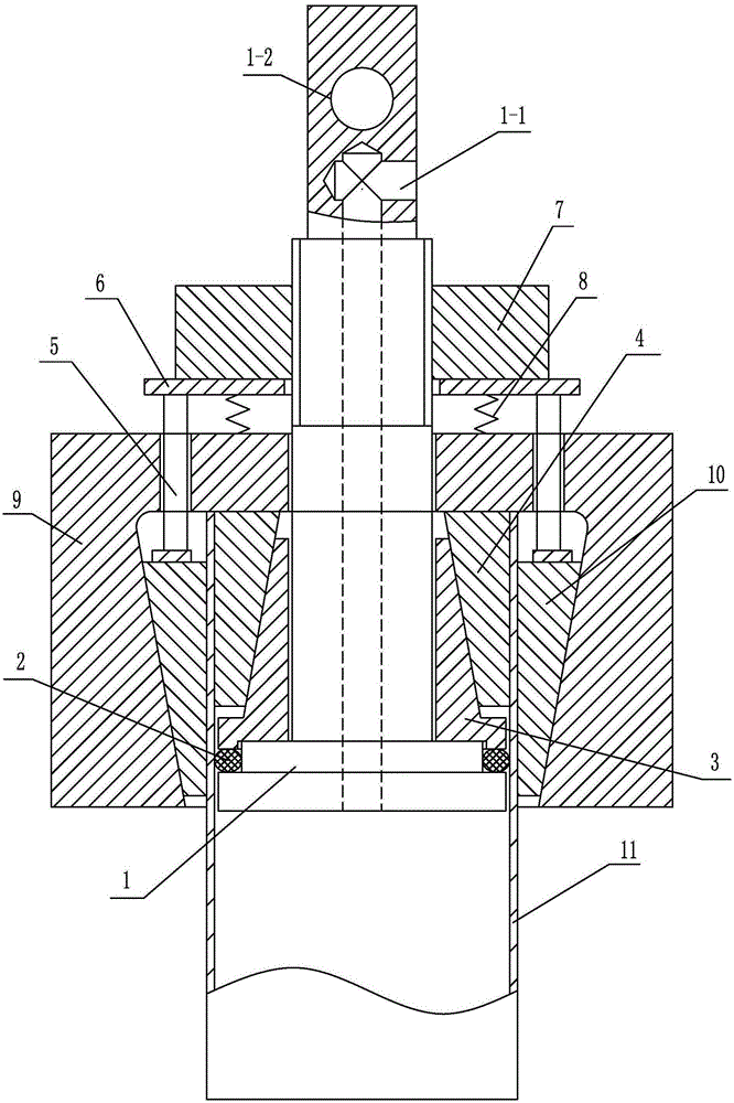
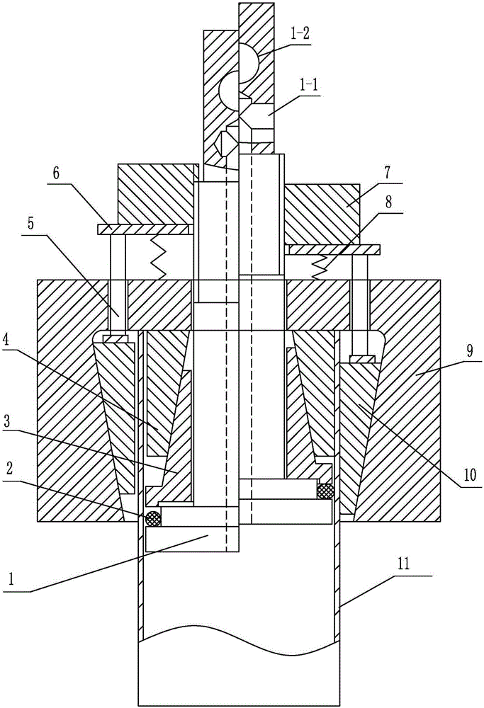
[0010] Specific implementation mode one: combine figure 1 and image 3 Explain that a pipe end clamping and sealing fixture in this embodiment includes a mandrel 1, a sealing ring 2, a wedge block 3, a supporting plate 6, a screw 7, an elastic element 8, an outer collar 9, and N Wedge-shaped inner jaws 4, N wedge-shaped outer jaws 10 and N ejector pins 5; wherein N is a positive integer, and 8≥N≥3; the mandrel 1 is a mandrel with a liquid-filled channel, and one end of the mandrel 1 is two Stepped structure, the other end of the mandrel 1 is processed with a liquid filling port 1-1 connected with the liquid filling channel; the middle section of the mandrel 1 is processed with external threads;

[0011] The screw 7 is threadedly connected to the middle section of the mandrel 1, and the mandrel 1 is covered with an outer collar 9, and a wedge block 3, N wedge-shaped inner jaws 4 and N Wedge-shaped outer claws 10; wedge-shaped blocks 3 are inserted on the mandrel 1, N wedge-sh...

Example Embodiment

[0014] Specific implementation mode two: combination figure 1 and image 3 Note that the elastic element 8 in this embodiment is a coil spring. With such arrangement, it is cheap and easy to obtain, and convenient to use and disassemble. Others are the same as in the first embodiment.

Example Embodiment

[0015] Specific implementation mode three: combination figure 1 and image 3 Note that the sealing ring 2 of this embodiment is an O-ring. With such arrangement, it is cheap and easy to obtain, simple in structure and convenient to use. Others are the same as in the first or second embodiment.


PUM


Abstract

The invention relates to a clamping and sealing clamp, in particular to a clamping and sealing clamp for the end of a pipe in order to solve the problems that due to the fact that clamping and sealing are mutually independent in an existing pipe tensioning-expanding test experiment and are mutually affected when in use, smooth conduction of the experiment is difficult to guarantee, clamping and sealing of the pipe can not be effectively combined, and the accuracy of the pipe performance experiment is affected. The clamping and sealing clamp comprises a mandrel, a sealing ring, a wedge-shaped block, a carrier plate, a screwing part, an elastic element, an outer clamping ring, N wedge-shaped inner claws, N wedge-shaped outer claws and N ejection rods. The screwing part is in threaded connection with the other end of the mandrel. The mandrel is sleeved with the outer clamping ring. The wedge-shaped block, the N wedge-shaped inner claws and the N wedge-shaped outer claws are arranged between the outer clamping ring and the mandrel. The N wedge-shaped inner claws and the N wedge-shaped outer claws are arranged in the peripheral direction of the mandrel. The part, between the screwing part and the outer clamping ring, of the mandrel is sleeved with the carrier plate and the elastic element. The elastic element abuts against the carrier plate and the outer clamping ring. The clamping and sealing clamp is used for clamping and sealing the end of the pipe during a pipe tensioning-expanding test experiment.

Description

technical field [0001] The invention relates to a clamping and sealing fixture, in particular to a clamping and sealing structure at the end of a pipe used in a pipe pull-expansion test experiment. Background technique [0002] The stretch-expansion test is a method to test the performance of the pipe. In the pipe stretch-expansion test, the end of the pipe must be clamped to apply axial force and ensure sealing to apply internal pressure. Therefore, the clamping and sealing of the end of the pipe is the key to the realization of the pipe tension-expansion test, and the two are related to each other, which directly affects the accuracy of the pipe tension-expansion test. There are two commonly used clamping methods: one is to put a mandrel slightly smaller than the inner diameter of the pipe inside the pipe end as an internal support, and then use a pair of semicircular or V-shaped clamps to clamp the outside of the pipe supported by the mandrel. tight. However, the clampi...

Claims


Application Information

Patent Timeline
IPC IPC(8): F16J15/06G01N3/04
Inventor 何祝斌朱海辉苑世剑
Owner HARBIN INST OF TECH
Why Eureka
Try Eureka