floating chuck

A technology of floating chuck and driving disc, which is applied in the field of machinery, can solve the problems of affecting the working efficiency of the grinding machine, general clamping effect, simple structure, etc., to improve machining accuracy and production efficiency, good clamping effect, and clamping force distribution uniform effect

Inactive Publication Date: 2016-09-21
NINGBO MEIDE ROBOT
View PDF7 Cites 0 Cited by
  • Summary
  • Abstract
  • Description
  • Claims
  • Application Information

AI Technical Summary

Problems solved by technology

In the prior art, most chucks suitable for grinding machines have a simple structure, general clamping effect and are easy to loosen during processing, which affects the working efficiency of the actual grinding machine

Method used


Image

  • floating chuck
  • floating chuck
  • floating chuck

Examples


Embodiment Construction

[0050] The following are specific embodiments of the present invention and in conjunction with the accompanying drawings, the technical solutions of the present invention are further described, but the present invention is not limited to these embodiments.

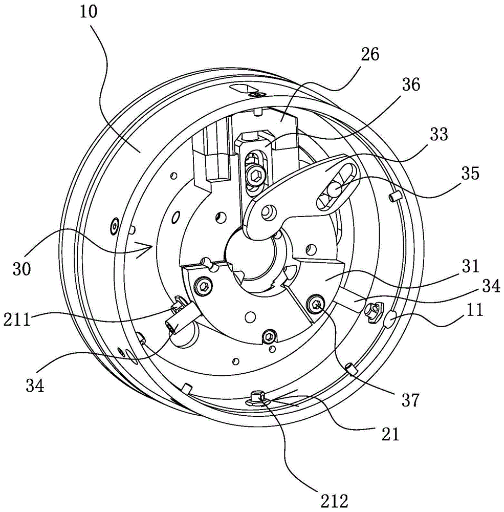
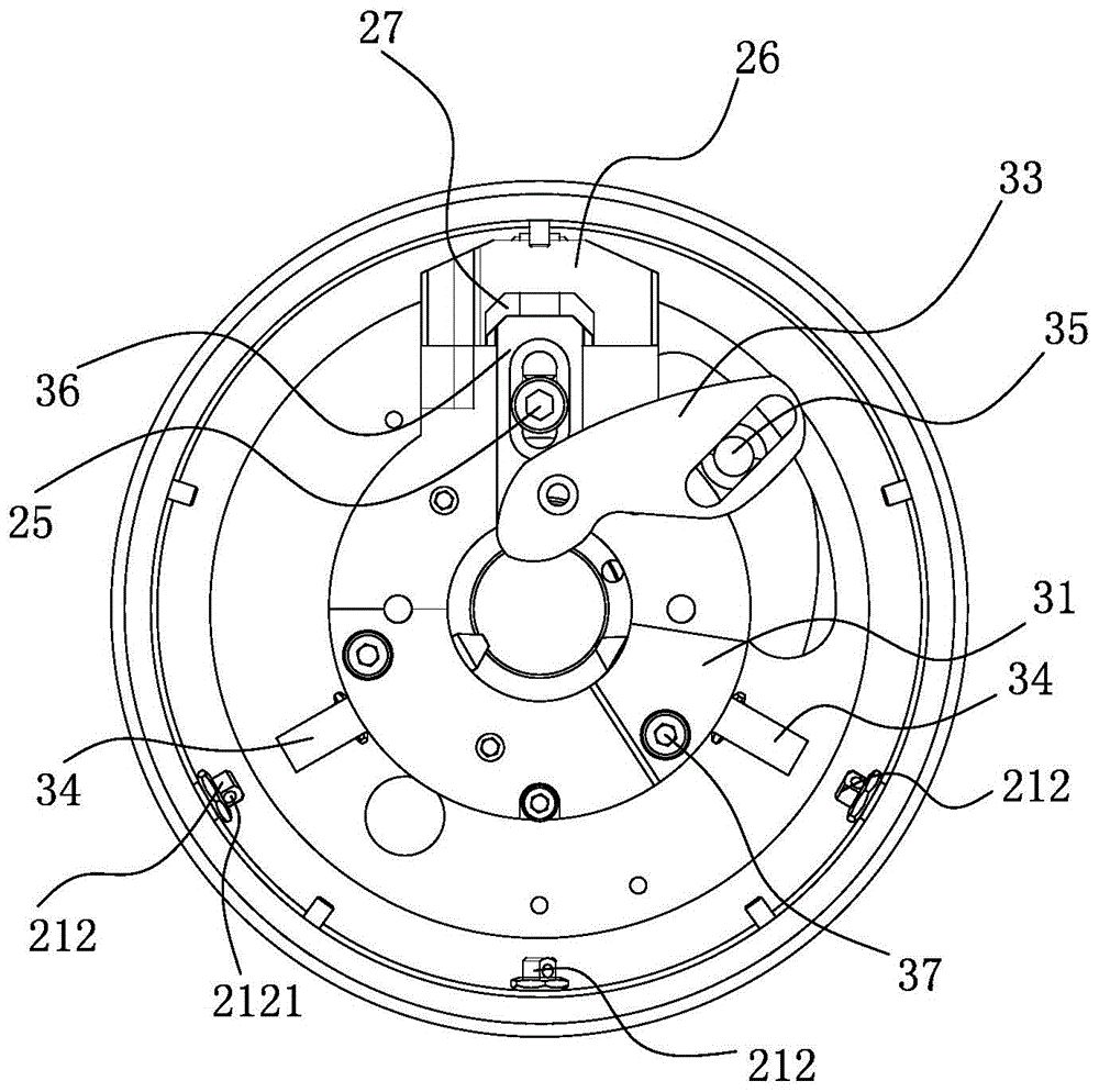
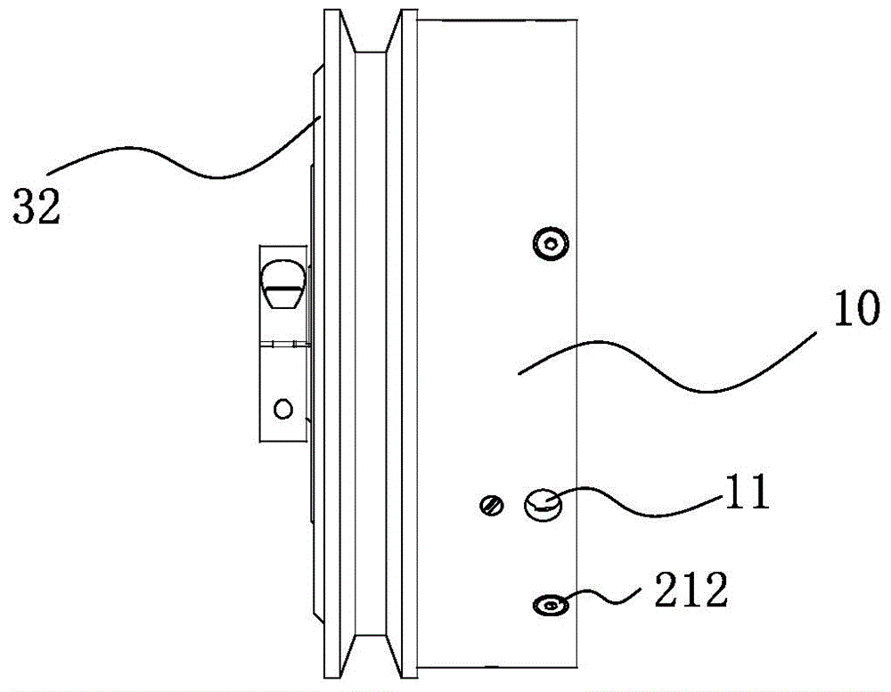
[0051] The invention protects a kind of floating chuck, which can be used to clamp the shaft workpiece of the grinding machine, which is convenient for the grinding machine to use the grinding tool to grind the surface of the workpiece to be processed. Of course, the chuck of the present invention can also be used to clamp similar shaft parts . Most of the existing collets have simple structural design, poor clamping effect and easy loosening of the workpiece during processing, which affects the working efficiency of the actual machine tool. Therefore, it is necessary to design a more reasonable floating chuck.

[0052] Such as Figure 1 to Figure 21 As shown, the floating chuck includes a housing 10, a driving mechanism...


PUM


Abstract

The invention provides a floating clamp and belongs to the technical field of machinery. The floating clamp comprises a shell, a drive mechanism and a clamping mechanism for clamping a workpiece. The clamping mechanism comprises a hollow fixing seat disposed in the shell and a drive plate. A main clamping part and a plurality of auxiliary clamping parts are disposed in front of the fixing seat. The auxiliary clamping parts are respectively fixed on the fixing seat. The head end of the main clamping part is hinged to the fixing seat. The tail end of the main clamping part is connected with the drive plate. The fixing seat is movably connected with the shell through a plurality of floating adjusting parts. The drive plate can drive the main clamping part to swing peripherally so as to allow the head end of the main clamping part to rotate around a hinge point, the fixing seat is driven by the main clamping part to move peripherally in a preset peripheral floating range, and the fixing seat and the auxiliary clamping parts move close to or away from the workpiece. The drive mechanism is connected with the drive plate and can drive the same to rotate forwardly and reversely. The floating clamp is good in clamping effect and has a floating adjusting function.

Description

technical field [0001] The invention belongs to the technical field of machinery and relates to a collet, in particular to a floating collet suitable for a grinding machine. Background technique [0002] A grinder is a machine tool that uses abrasive tools to grind the surface of a workpiece. Most grinding machines use high-speed rotating grinding wheels for grinding, and a few use other abrasive tools such as oil stones, abrasive belts, and free abrasives for processing. [0003] When grinding shaft workpieces, use double clamping parts to support the shaft to be processed on the machine tool, install a chuck at one end of the shaft, and fix the chuck with the shaft to be processed, and the machine tool drives the grinding wheel close to the shaft for grinding. In the prior art, most chucks suitable for grinding machines have a simple structure, general clamping effect and easy loosening during processing, which affects the actual working efficiency of the grinding machine...

Claims


Application Information

Patent Timeline
Patent Type & Authority Patents(China)
IPC IPC(8): B24B41/06
CPCB24B41/062
Inventor 翁海明
Owner NINGBO MEIDE ROBOT
Why Eureka
Try Eureka