
Bit detection device

A technology of detection device and drill bit, applied in the direction of measurement device, mechanical measurement device, using mechanical device, etc., can solve the problems of detection and low versatility

Inactive Publication Date: 2015-12-23
SUZHOU ANTAUR AUTOMATION EQUIP
View PDF12 Cites 7 Cited by
  • Summary
  • Abstract
  • Description
  • Claims
  • Application Information

AI Technical Summary

Problems solved by technology

The existing drill detection device only has a measurement angle of a specific angle, and can only detect one type of drill. For drills with different main cutting edge angles, the detection device cannot detect them, and the versatility is low

Method used


Image

  • Bit detection device
  • Bit detection device
  • Bit detection device

Examples


Embodiment Construction

[0019] The specific implementation manners of the present invention will be further described in detail below in conjunction with the accompanying drawings and embodiments. The following examples are used to illustrate the present invention, but are not intended to limit the scope of the present invention.

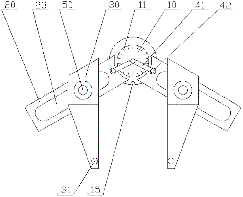
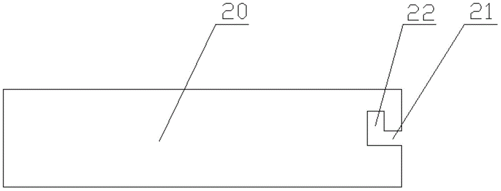
[0020] see Figure 1 to Figure 3 , a drill detection device described in a preferred embodiment of the present invention includes two measuring plates 20 respectively rotatably connected to the dial 10, and a positioning plate 30 slidingly connected to the two measuring plates 20 respectively.

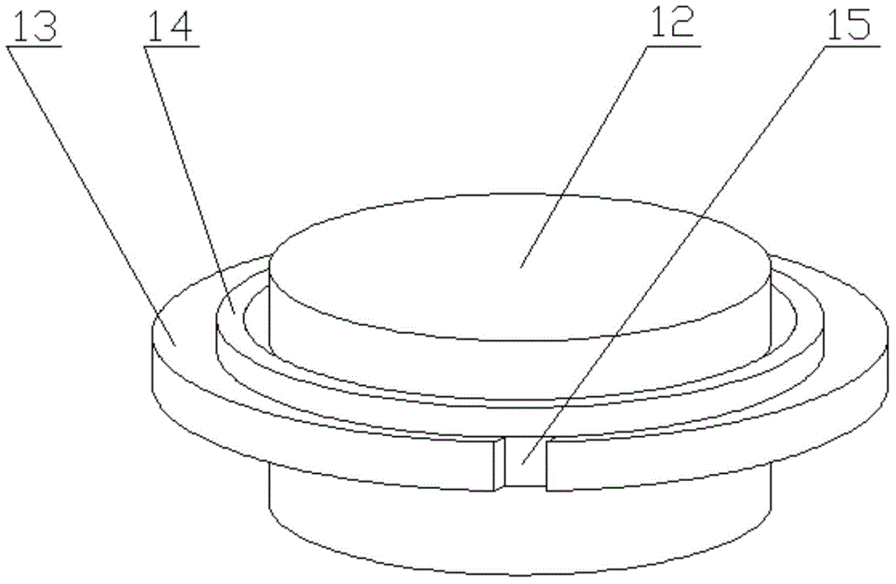
[0021] Specifically, the dial 10 includes a disk 12 provided with an angle index line 11, a circular ring 13 coaxial with the circular disk 12 is provided on the outer periphery of the circular disk 12, and an annular sliding bar 14 coaxial with the circular ring 13 is vertically connected thereto. The side wall of the ring 13 is provided with positioning grooves 15 along its radi...


PUM


Abstract

The invention relates to a bit detection device, which comprises two measurement plates in rotation connection with a dial respectively and positioning plates in sliding connection with the two measurement plates respectively. The side wall of the dial is provided with a positioning groove for clamping two main cutting edge end heads of the bit. The dial is also in rotation connection with two pressing devices capable of fixing the two measurement plates on the dial respectively. According to the bit detection device, through enabling the two measurement plates and the dial to be in rotation connection, the included angle between the measurement plates can be adjusted, and a bit with a different specification can be detected; according to the coincidence degree between the transverse edge of the bit and the positioning groove, and the fit degree between the two main cutting edges and the measurement plates and the positioning plate, whether the transverse edge of the bit after grinding is in the center can be detected, whether angles and lengths of the two main cutting edges are consistent is detected, universality is high, and measurement is accurate.

Description

technical field [0001] The invention relates to the technical field of drill bit detection, in particular to a drill bit detection device. Background technique [0002] A drill is a tool used to drill through holes or blind holes in solid materials and to ream existing holes. The drill bit includes a tool shank and two main cutting edges located at the head of the tool shank, and a chisel edge is sandwiched between the two main cutting edges. [0003] During the use of the drill bit, the two main cutting edges and the chisel edge of the head wear the fastest. Therefore, the main cutting edge needs to be ground after it is worn. The traditional method is to manually grind the flanks of the two main cutting edges of the drill on a grinder based on experience. Errors will occur during the grinding process. The larger the diameter of the drill, the greater the error, resulting in the two sides of the drill after grinding. Inconsistent main cutting edge angle and length. [00...

Claims


Application Information

Patent Timeline
IPC IPC(8): G01B5/02G01B5/24G01B5/00
Inventor 吴海峰
Owner SUZHOU ANTAUR AUTOMATION EQUIP
Learn More