High-speed train eddy current brake performance test device and method

A technology of eddy current braking and high-speed trains, which is applied in the direction of railway vehicle testing, etc., can solve the problems that the high-power eddy current braking test of high-speed trains cannot be satisfied, the test requirements are difficult to meet, and the test speed is not high, so as to improve the test speed and suppress the temperature. Up, to achieve the effect of stepless adjustment

Active Publication Date: 2015-12-23
CHINA ACADEMY OF RAILWAY SCI CORP LTD +2
View PDF8 Cites 15 Cited by
  • Summary
  • Abstract
  • Description
  • Claims
  • Application Information

AI Technical Summary

Problems solved by technology

These two test devices are suitable for the principle test and verification of electromagnetic eddy current braking. The structure of the brake electromagnet is fixed, the test speed is not high, the test inertia is small and cannot be adjusted, and i

Method used


Image

  • High-speed train eddy current brake performance test device and method
  • High-speed train eddy current brake performance test device and method

Examples


Embodiment approach 1

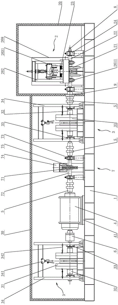
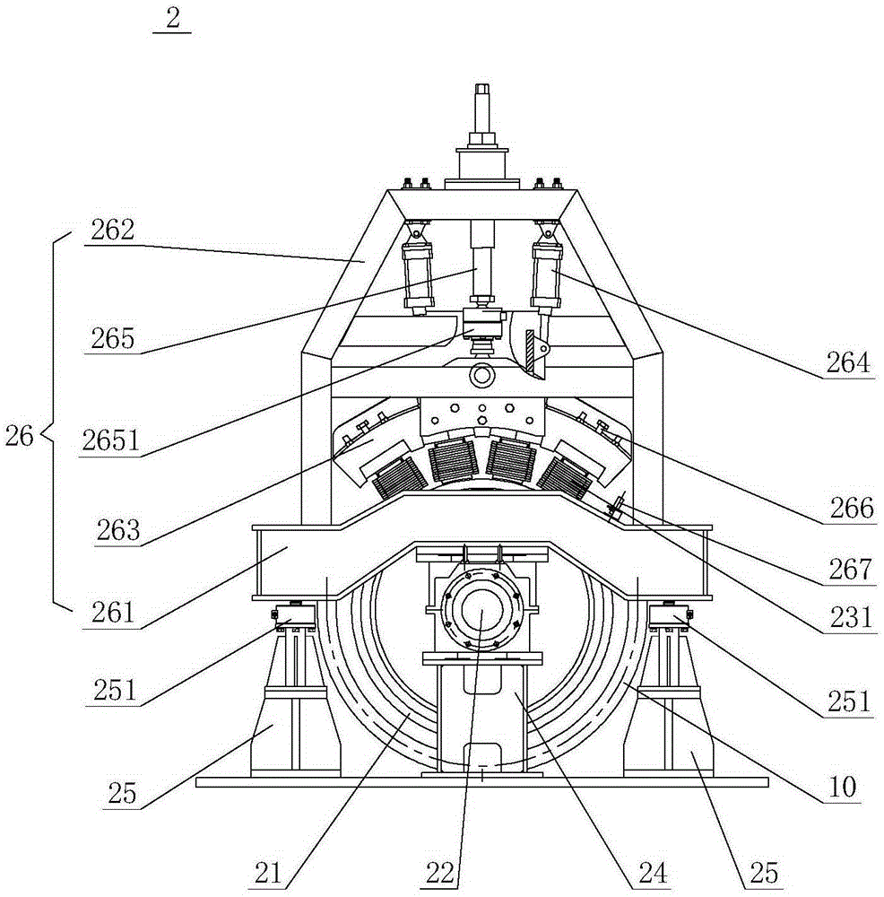
[0055] Such as figure 1 As shown, the present invention provides a kind of eddy current brake performance test device, and it comprises base 1, track wheel unit 2, mechanical inertia unit 3 and driving motor 4, wherein: base 1 is fixedly connected with concrete foundation; Track wheel unit 2 is connected on On the base 1, it has a track wheel 21, the track wheel 21 is connected to a track wheel shaft 22, and a brake magnet group 23 is arranged above the track wheel 21; the mechanical inertia unit 3 is connected to the base 1 , which has a plurality of movable flywheels 31, the movable flywheels 31 are connected to a flywheel shaft 32, and the flywheel shaft 32 is connected to the track wheel shaft 22 through a coupling 5; the drive motor 4 is connected to the base 1 , it is connected with the flywheel shaft 32 through a shaft coupling 5 or a clutch 6 .

[0056] Specifically, the base 1 provides support for the track wheel unit 2, the mechanical inertia unit 3 and the driving ...

Embodiment approach 2

[0083] Such as figure 1 with figure 2 As shown, the present invention also provides a high-speed train eddy current braking performance test method, the high-speed train eddy current braking performance test method adopts the high-speed train eddy current braking performance test device of Embodiment 1, and the high-speed train eddy current braking performance test device The structure, working principle and beneficial effects of the performance test device are the same as those of Embodiment 1, and will not be repeated here. Described high-speed train eddy current braking performance test method comprises the steps:

[0084] a) configure the quantity of the movable flywheel 31 on the mechanical inertia unit 3 and the mechanical inertia unit 3 as required; start the drive motor 4, and the drive motor 4 drives the track wheel 21 of the mechanical inertia unit 3 and the track wheel unit 2 to rotate and Reach the actual vehicle speed, simulate the relative motion between the t...


PUM


Abstract

The invention provides a high-speed train eddy current brake performance test device and method. The high-speed train eddy current brake performance test device comprises a base which is fixedly connected with a concrete base, a track wheel unit which is connected with the base, a mechanical inertia unit and a drive motor. The track wheel unit comprises a track wheel. The track wheel is connected with a track wheel shaft. A brake magnet group is arranged above the track wheel. The mechanical inertia unit is connected with the base, and comprises a number of movable flywheels. The movable flywheels are connected with a flywheel shaft. The flywheel shaft is connected with the track wheel shaft through a coupling. The drive motor is connected with the base. The drive motor is connected with the flywheel shaft through a coupling or a clutch. The high-speed train eddy current brake performance test device and method, which are provided by the invention, can simulate relative motion between a train and a track, and have the advantages of high test speed, large load inertia, continuously adjustable inertia, high safety and test efficiency and the like.

Description

technical field [0001] The invention relates to a rail vehicle eddy current braking performance test device and method, in particular to a high-speed train eddy current braking performance test device and method applied in the technical field of high-speed train braking. Background technique [0002] Braking technology is one of the key technologies of high-speed trains. Due to the huge braking energy of high-speed trains, and the wheel-rail adhesion coefficient gradually decreases with the increase of speed, it is difficult to achieve safe stopping and energy conversion within the specified braking distance. . All high-speed trains in the world adopt a composite braking mode with multiple braking methods. The main braking methods include regenerative braking, resistance braking, friction braking, eddy current braking, magnetic rail braking and aerodynamic braking, etc. . my country's EMUs use regenerative braking and friction braking (disc braking), which are the most wid...

Claims


Application Information

Patent Timeline
IPC IPC(8): G01M17/08
Inventor 丁福焰李和平宋跃超李辉王可
Owner CHINA ACADEMY OF RAILWAY SCI CORP LTD
Why Eureka
Try Eureka