GIA circuit and display device

A gate drive circuit and gate drive technology, applied in the direction of static indicators, instruments, etc., can solve the problems of large fluctuations in TFT characteristics, poor circuit stability, and drop in on-state current, so as to reduce layout area occupancy, The effect of high stability and reduced threshold voltage drift

Active Publication Date: 2015-12-23
KUSN INFOVISION OPTOELECTRONICS
View PDF4 Cites 30 Cited by
  • Summary
  • Abstract
  • Description
  • Claims
  • Application Information

AI Technical Summary

Benefits of technology

This technology improves the performance of semiconductor devices used for data communication between different components on printed wiring boards (PWBs). By reducing temperature fluctuations during operation, this helps maintain stable power supply levels at higher speeds while also increasing device's reliability. Additionally, it simplifies the overall structure of the PWD system without adding extra parts or requiring more space than necessary. Overall, these improvements improve the efficiency and quality of electronic systems utilizing semiconducers such as computers.

Problems solved by technology

This patented technical solution described by this patents relates to improving the performance and lifespan of a semiconductor device called an LC filter or liquid crystal display (AML). These devices use Thinner Gate Liquid Crystal Display(TFT), where there are fewer lines between components compared to previous designs. Additionally, these circuits have lower leakage currents than older technologies like CMOS image sensor arrays, reducing their impact on signal quality during operation. By optimizing certain parameters within specific areas of the chip structure, we aimed at achieving higher efficiency and better functionality over existing products while minimizing costs associated with production processes.

Method used


Image

  • GIA circuit and display device
  • GIA circuit and display device
  • GIA circuit and display device

Examples


no. 1 example

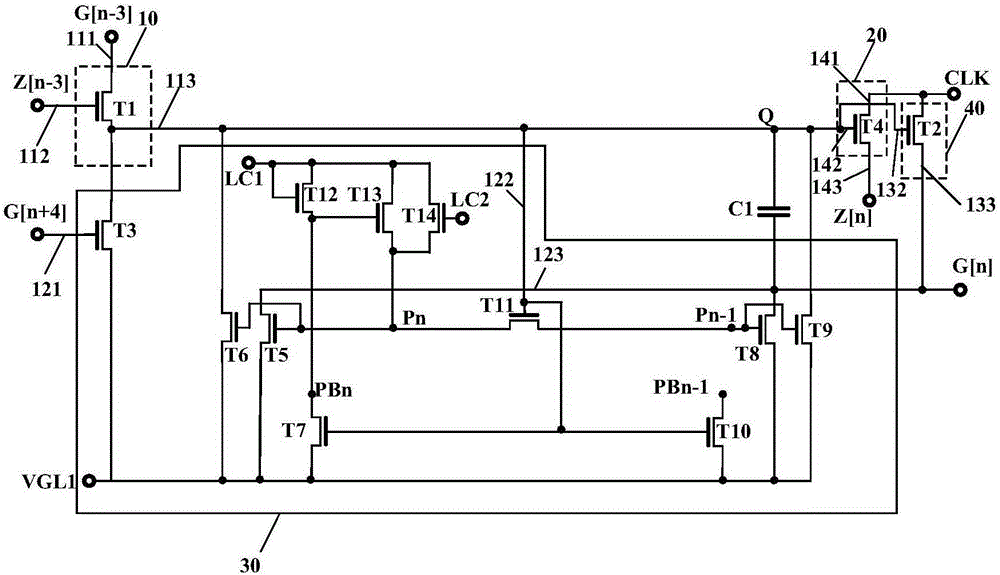
[0030] figure 1 is a circuit diagram of the gate drive unit circuit provided by the first embodiment of the present invention. see figure 1 , the gate driving unit circuit 5 includes: a pre-charging module 10 , a transfer signal generating module 20 , a stabilizing module 30 , and an output module 40 . Wherein, the pre-charging module 10 is electrically connected with the transfer signal generating module 20 , the stabilizing module 30 , and the output module 40 .

[0031] In the embodiments of the present invention, it is assumed that the current gate driving unit circuit is the nth-level gate driving unit circuit, and G[n] and Z[n] respectively represent the gate scanning signals output by the n-level gate driving unit circuit and transmission signal, G[n+1], Z[n+1] respectively represent the gate scanning signal and the transmission The signals, G[n-1] and Z[n-1] respectively represent the gate scanning signal and the transfer signal output by the gate driving unit circu...

no. 2 example

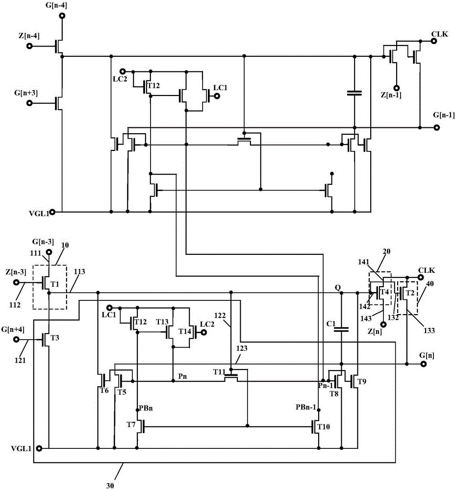
[0067] Figure 7 is a circuit diagram of the gate drive unit circuit provided by the second embodiment of the present invention. This embodiment and figure 1 The difference is that: the gate driving unit circuit of the first stage in the plurality of gate driving unit circuits may further include: transistors T15 (fifteenth transistor), T16 (sixteenth transistor) and T17 (tenth transistor seven transistors), and the first signal receiving end 111 and the second signal receiving end 112 are connected to the start signal output end STV to receive the start signal.

[0068] Wherein, the gate of the transistor T15 receives the first control signal LC1, the first terminal of the transistor T15 is electrically connected to the fourth node PB0 of the first stage gate driving unit circuit, and the second terminal of the transistor T15 receives the first control signal LC1 . The gate of the transistor T16 is electrically connected to the fourth node PB0 of the first-stage gate drive...

no. 3 example

[0071] According to the above embodiments, the third embodiment of the present invention also discloses a display device, including: a panel, the panel includes a two-dimensional pixel array composed of a plurality of pixels, and a plurality of pixels in the first direction connected to each pixel array A data line and a plurality of gate scanning lines in the second direction; a data driving circuit for providing image signals to the data lines; and a gate driving circuit in Embodiments 1 and 2 for scanning the gate line provides the gate scan signal. The pixel array is formed on a transparent substrate, and includes a plurality of gate lines, data lines and a plurality of switching transistors. Switch transistors are respectively coupled to each gate line and each data line. The data driving circuit is coupled to the data lines and provides data signals to the data lines. The gate drive circuit is coupled to the gate line and drives the switch transistor.

[0072] In summ...


PUM


Abstract

The embodiment of the invention discloses a GIA (Gate-driver In Array) circuit and a display device, belonging to the display driving technical field. The GIA circuit comprises a pre-charge module, a transmission signal generation module, a stabilizing module and an output module. When the transmission signal outputted by an (n-3)th level of GIA unit circuit becomes a high level form a low level, and the grid scanning signal outputted by the (n-3)th level of GIA unit circuit also becomes a high level form a low level, the pre-charge module charges a control node through an output terminal; when a clock signal becomes a high level form a low level, the transmission signal generation module performs charge pump on the control node, rising the potential of the control node; when the control node is pulled down to a low level, the stabilizing module pulls down and stabilizes the control node and the output terminal; when the control node is a high level, the low level of the clock signal is applied to a grid scanning signal output terminal. According to the invention, the circuit output capability and stability are improved.

Description


Claims


Application Information

Patent Timeline
Owner KUSN INFOVISION OPTOELECTRONICS
Why Eureka
Try Eureka