Gate drive circuit and display device
A gate drive circuit and gate drive technology, applied in static indicators, instruments, etc., can solve the problems of large variation in TFT characteristics, poor circuit stability, and drop in on-state current, so as to reduce the occupation of layout area, High stability and reduced threshold voltage drift effect
- Summary
- Abstract
- Description
- Claims
- Application Information
AI Technical Summary
Problems solved by technology
Method used
Image
Examples
no. 1 example
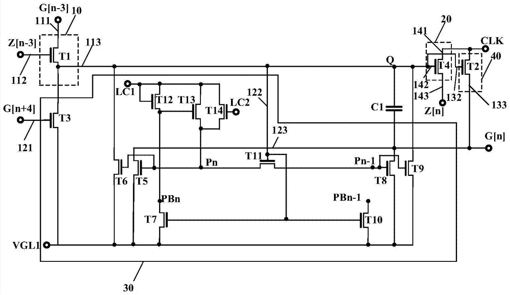
[0030] figure 1 is a circuit diagram of the gate drive unit circuit provided by the first embodiment of the present invention. see figure 1 , the gate driving unit circuit 5 includes: a pre-charging module 10 , a transfer signal generating module 20 , a stabilizing module 30 , and an output module 40 . Wherein, the pre-charging module 10 is electrically connected with the transfer signal generating module 20 , the stabilizing module 30 , and the output module 40 .
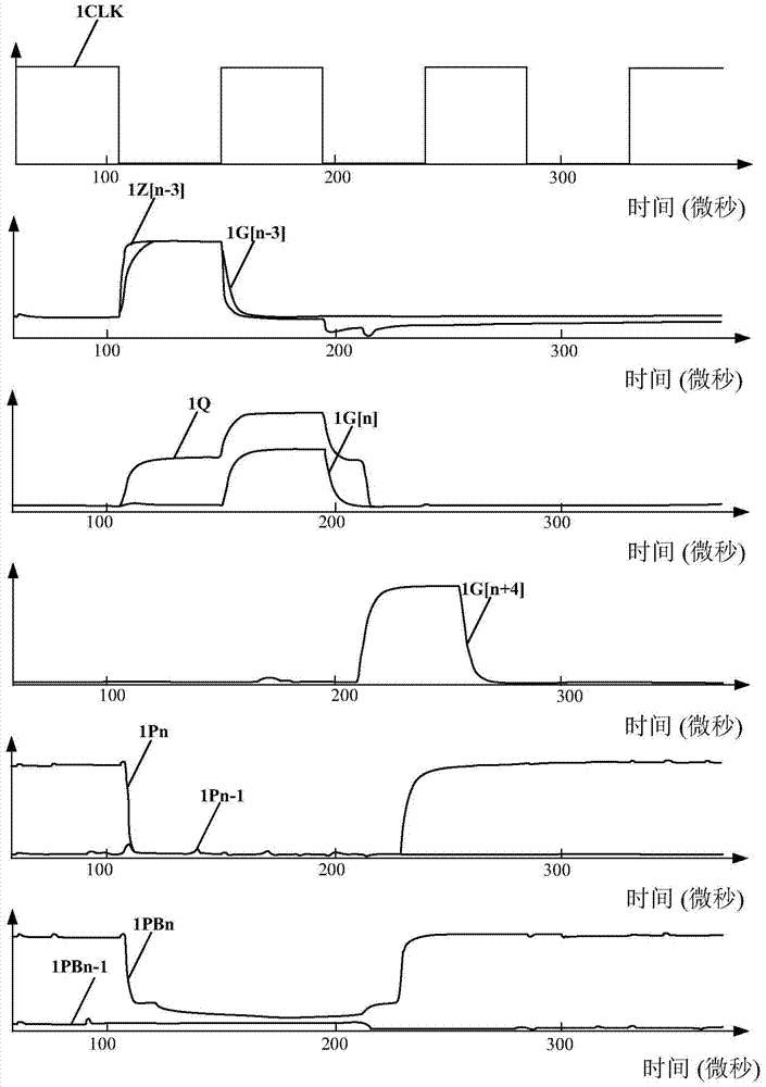
[0031] In the embodiments of the present invention, it is assumed that the current gate driving unit circuit is the nth-level gate driving unit circuit, and G[n] and Z[n] respectively represent the gate scanning signals output by the n-level gate driving unit circuit and transmission signal, G[n+1], Z[n+1] respectively represent the gate scanning signal and the transmission The signals, G[n-1] and Z[n-1] respectively represent the gate scanning signal and the transfer signal output by the gate driving unit circu...
no. 2 example
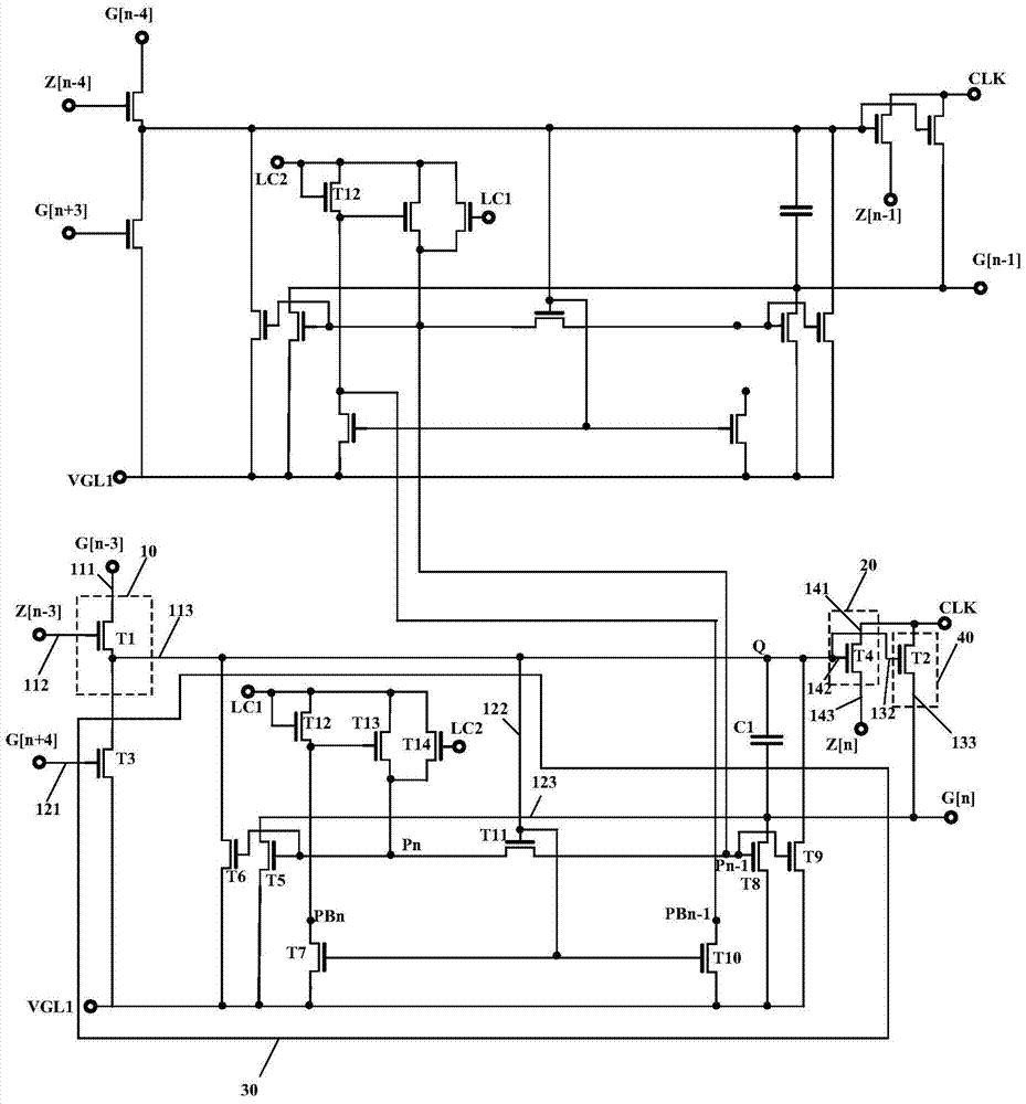
[0067] Figure 7 is a circuit diagram of the gate drive unit circuit provided by the second embodiment of the present invention. This embodiment and figure 1 The difference is that: the gate driving unit circuit of the first stage in the plurality of gate driving unit circuits may further include: transistors T15 (fifteenth transistor), T16 (sixteenth transistor) and T17 (tenth transistor seven transistors), and the first signal receiving end 111 and the second signal receiving end 112 are connected to the start signal output end STV to receive the start signal.
[0068] Wherein, the gate of the transistor T15 receives the first control signal LC1, the first terminal of the transistor T15 is electrically connected to the fourth node PB0 of the first stage gate driving unit circuit, and the second terminal of the transistor T15 receives the first control signal LC1 . The gate of the transistor T16 is electrically connected to the fourth node PB0 of the first-stage gate drive...
no. 3 example
[0071] According to the above embodiments, the third embodiment of the present invention also discloses a display device, including: a panel, the panel includes a two-dimensional pixel array composed of a plurality of pixels, and a plurality of pixels in the first direction connected to each pixel array A data line and a plurality of gate scanning lines in the second direction; a data driving circuit for providing image signals to the data lines; and a gate driving circuit in Embodiments 1 and 2 for scanning the gate line provides the gate scan signal. The pixel array is formed on a transparent substrate, and includes a plurality of gate lines, data lines and a plurality of switching transistors. Switch transistors are respectively coupled to each gate line and each data line. The data driving circuit is coupled to the data lines and provides data signals to the data lines. The gate drive circuit is coupled to the gate line and drives the switch transistor.
[0072] In summ...
PUM
 Abstract
Description
Claims
Application Information
 - R&D
- Intellectual Property
- Life Sciences
- Materials
- Tech Scout
- Unparalleled Data Quality
- Higher Quality Content
- 60% Fewer Hallucinations
Browse by: Latest US Patents, China's latest patents, Technical Efficacy Thesaurus, Application Domain, Technology Topic, Popular Technical Reports.
© 2025 PatSnap. All rights reserved.Legal|Privacy policy|Modern Slavery Act Transparency Statement|Sitemap|About US| Contact US: help@patsnap.com


