A kind of rare earth permanent magnet transmission clutch

A rare-earth permanent magnet and clutch technology, applied in the field of clutches, can solve problems such as vibration noise, friction loss, and reduced sealing performance, and achieve the effects of simple structure, no need for lubrication, and high reliability

Active Publication Date: 2018-07-24
芜湖磁轮传动技术有限公司
View PDF5 Cites 0 Cited by
  • Summary
  • Abstract
  • Description
  • Claims
  • Application Information

AI Technical Summary

Problems solved by technology

Since the hydraulic clutch uses oil as the transmission medium, it is easy to cause oil leakage and high failure rate
[0003] Moreover, after the general clutch is engaged, it cannot change the speed, and it is necessary to add a gearbox to adjust the speed and torque. The stability of the mechanical movement can only be guaranteed by lubricating with oil, but after a long time, the sealing performance will be reduced due to mechanical vibration or wear, resulting in oil leakage

Method used


Image

  • A kind of rare earth permanent magnet transmission clutch
  • A kind of rare earth permanent magnet transmission clutch
  • A kind of rare earth permanent magnet transmission clutch

Examples


Embodiment 1

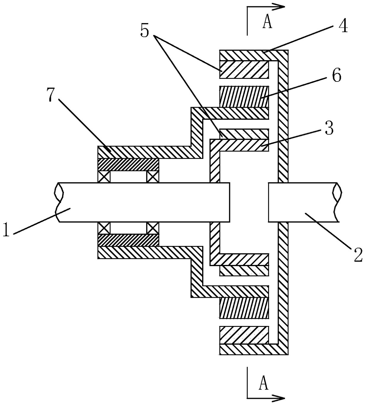
[0019] see figure 1 and Figure 5 As shown, a rare earth permanent magnet transmission clutch includes a first shaft body 1 and a second shaft body 2, the shaft end of the first shaft body 1 is equipped with an inner magnetic rotor 3 that rotates synchronously with the first shaft body 1, The shaft end of the second shaft body 2 and the position corresponding to the inner magnetic rotor 3 are installed with an outer magnetic rotor 4 that rotates synchronously with the second shaft body 2, and permanent magnets 5 are distributed on the outer wall of the inner magnetic rotor 3. The N-level and S-level magnets are arranged alternately, and the permanent magnets 5 are also distributed on the inner wall of the outer magnetic rotor 4, and the N-level and S-level permanent magnets are also arranged alternately. The outer magnetic rotor 4 and the inner magnetic rotor 3 are sleeved with The modulation ring 6, the modulation ring 6 is composed of magnetic modulation materials distribut...

Embodiment 2

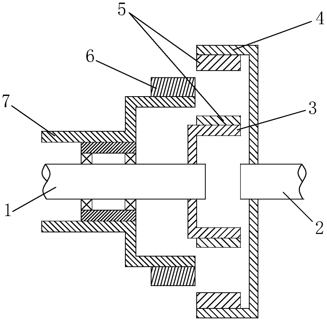
[0022] see image 3 As shown, a rare earth permanent magnet transmission clutch includes a first shaft body 1 and a second shaft body 2, the shaft end of the first shaft body 1 is equipped with an inner magnetic rotor 3 that rotates synchronously with the first shaft body 1, The shaft end of the second shaft body 2 and the position corresponding to the inner magnetic rotor 3 are installed with an outer magnetic rotor 4 that rotates synchronously with the second shaft body 2, and permanent magnets 5 are distributed on the outer wall of the inner magnetic rotor 3. The N-level and S-level magnets are arranged alternately, and the permanent magnets 5 are also distributed on the inner wall of the outer magnetic rotor 4, and the N-level and S-level permanent magnets are also arranged alternately. The outer magnetic rotor 4 and the inner magnetic rotor 3 are sleeved with The modulation ring 6, the modulation ring 6 is composed of magnetic modulation materials distributed at intervals...


PUM


Abstract

The invention, which belongs to the technical field of clutch, discloses a rare-earth permanent-magnet speed-changing clutch comprising a first shaft body, a second shaft body and a modulation ring. An internal magnetic rotor rotating synchronously with the first shaft body is installed at the shaft end of the first shaft body; and an external magnetic rotor rotating synchronously with the second shaft body is installed at the shaft end of the second shaft body by corresponding to the internal magnetic rotor. The modulation ring is arranged between the external magnetic rotor and the internal magnetic rotor; and an adjusting device is fixedly connected with the modulation ring. When the adjusting device is adjusted, the modulation ring makes axial movement along the first shaft body to change an action area between the internal magnetic rotor and the external magnetic rotor, thereby changing the transmission torque between the internal magnetic rotor and the external magnetic rotor. According to the invention, transmission and disconnection of a torque can be realized; and a speed reduction or increasing effect can be realized during the torque transmission process. Moreover, the rare-earth permanent-magnet speed-changing clutch has advantages of simple structure, contact-free torque transmission, wearing prevention, lubrication avoidance, underloading starting, overload protection, and high reliability and the like.

Description

technical field [0001] The invention belongs to the technical field of clutches, and relates to a clutch with a permanent magnet transmission function, in particular to a rare-earth permanent magnet transmission clutch with exquisite structure, stable operation and good reliability. Background technique [0002] The clutch is a component that cuts off or reconnects the transmission components to determine the timing of power input. Due to the use of mechanical coordination for transmission, the traditional mechanical clutch will produce some irreversible problems, such as mechanical fatigue, friction loss, vibration noise, etc., must be lubricated with lubricating oil to ensure the stability of mechanical movement, but it will last for a long time After that, the sealing performance will be reduced due to mechanical vibration or wear, resulting in oil leakage. Since the electromagnetic clutch needs to be connected to the circuit, its use range is narrow, and it depends on t...

Claims


Application Information

Patent Timeline
Patent Type & Authority Patents(China)
IPC IPC(8): H02K49/10
Inventor 王向东周丽萍
Owner 芜湖磁轮传动技术有限公司
Why Eureka
Try Eureka