
Battery processing detecting device with heat dissipating function

A detection device and battery technology, applied in the direction of measuring device, measuring device shell, measuring electricity, etc., can solve the problems of poor selectability, low detection efficiency, long-term interval of analog circuits, etc., and achieve increased friction and rich Simulate the experimental environment and improve the effect of the experimental variable environment

Inactive Publication Date: 2018-12-21
DONGGUAN UNIV OF TECH
View PDF0 Cites 2 Cited by
  • Summary
  • Abstract
  • Description
  • Claims
  • Application Information

AI Technical Summary

Problems solved by technology

[0004] The purpose of the present invention is to provide a battery processing and testing device with a heat dissipation function to solve the limitations of the modern battery testing device proposed in the background technology above in terms of its own structure, specifically in the various working forms of the battery The detection simulation is not comprehensive or in-depth, and the degree is low. The analog circuit of the battery is poor in transferability and selectability. For the simulation of complex circuits, a detection device cannot quickly achieve the purpose of simulation. The analog circuit There is a long time interval between switching, resulting in low detection efficiency. In the detection process, it is also necessary to consider the assistance of the detection device for the detection process, that is, the device itself should provide services for the detection as much as possible, but modern The detection device is relatively deficient in this respect

Method used


Image

  • Battery processing detecting device with heat dissipating function
  • Battery processing detecting device with heat dissipating function
  • Battery processing detecting device with heat dissipating function

Examples


Embodiment Construction

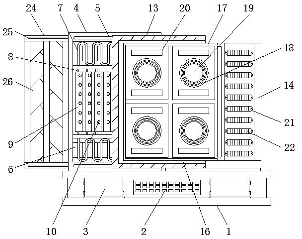
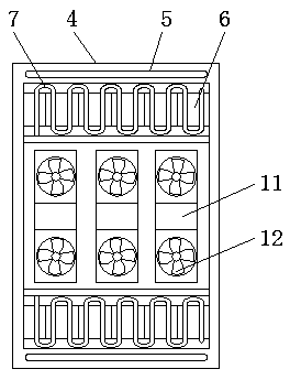
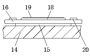
[0028] The technical solutions in the embodiments of the present invention will be clearly and completely described below in conjunction with the accompanying drawings in the embodiments of the present invention. Obviously, the described embodiments are only some of the embodiments of the present invention, not all of them. Based on The embodiments of the present invention and all other embodiments obtained by persons of ordinary skill in the art without making creative efforts belong to the protection scope of the present invention.

[0029] see Figure 1-6, the present invention provides a technical solution: a battery processing and testing device with heat dissipation function, including a base 1 and a first auxiliary box 13, an adapter terminal board 2 is installed in the middle of the surface of the base 1, and the adapter terminal board 2 The left and right sides are all provided with power supply boxes 3, and the top of the base 1 is fixed with a heat dissipation box 4...


PUM


Abstract

The invention discloses a battery processing detecting device with a heat dissipating function. The battery processing detecting device comprises a base and a first auxiliary box. A patch cord board is mounted in the middle of the surface of the base, and power supplying boxes are arranged on the left and right sides of the patch cord board correspondingly. A heat dissipating box is fixed to the upper portion of the base, and a pulling board is arranged in the first auxiliary box which is located on the front side of the heat dissipating box. According to the battery processing detecting device with the heat dissipating function, through arrangement of the heat dissipating box, the whole detecting device is provided with a relatively concentrated and average heat dissipating structure, theheat dissipating structure and a detecting structure are separated from each other, and thus normal conducting of detecting work is ensured. The heat dissipating box has two heat dissipating modes, one of the two heat dissipating modes is air cooling, and the other heat dissipating mode is water cooling. A cooling medium can be introduced into a U-shaped pipe, the U-shaped pipe and sliding platesare fixedly connected, the sliding plates can relatively slide, through sliding of the sliding plates, the U-shaped pipe extends, stretches out and draws back in the horizontal direction, and the acting area of the U-shaped pipe is changed.

Description

technical field [0001] The invention relates to the technical field of battery processing and testing equipment, in particular to a battery processing and testing device with a heat dissipation function. Background technique [0002] A battery refers to a cup, tank or other container or a part of a composite container that contains an electrolyte solution and a metal electrode to generate current. It is a device that can convert chemical energy into electrical energy. It has a positive pole and a negative pole. With the advancement of technology, the battery It generally refers to small devices that can generate electric energy, such as solar cells. Batteries can be seen almost everywhere in modern people's lives and have a wide range of applications. In the production and processing of batteries, because batteries are products of power supply, In the later period, it is particularly important to inspect the individual batteries. The purpose of the inspection is to obtain be...

Claims


Application Information

Patent Timeline
IPC IPC(8): G01R31/36G01R1/04H05K7/20
CPCG01R1/04H05K7/20136H05K7/20272
Inventor 邓君徐进甄超孙德凤
Owner DONGGUAN UNIV OF TECH
Learn More