A method of controlling a lighting arrangement, a lighting controller and a lighting system

A lighting device and controller technology, which is applied in the field of lighting systems, can solve problems such as inability to install and large capacitors, and achieve the effects of improving efficiency, minimizing peak power, and improving power factor

Active Publication Date: 2015-12-23
SIGNIFY HOLDING B V
7 Cites 6 Cited by

AI-Extracted Technical Summary

Problems solved by technology

In this case the capacitor may be...

Method used

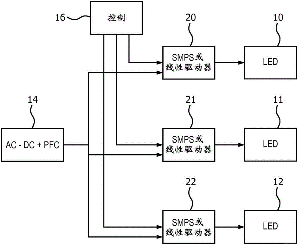
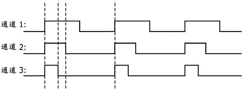
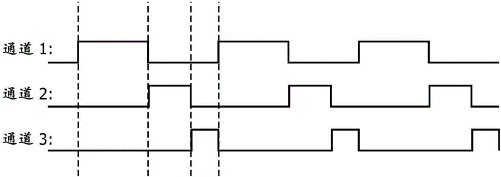
[0079] The present invention provides a lighting controller and method in which light sources are activated in a repeating phenanthrene overlapping sequence for repeated durations. The end of the duration for one light source is detected to trigger switching on of the next light source in the sequence. This provides non-overlapping control of light sources and provides an efficient and easy to implement required controller.
[0081] Each channel triggers the next channel, and since the repeating sequence is defined, the last channel in one cycle triggers the first channel in the next cycle. By providing no overlap between channels, the peak power in each cycle is equal to the maximum peak power of each channel. Peak power can thus be limited, resulting in low power requirements for the AC-DC driver, reducing space requirements.
[0084] To control the channel, only the start command for channel 1 needs to be activated. No other reference timing signal is required. For each channel, the duty cycle or duration of ON (ON) can be preset. Thus, after being triggered, each channel is turned on for the preset duration and then turned off. Operation is thus a simple operation which can be done by any microprocessor/microcontroller, including low end/low cost versions.
[0095] In order to reduce output ripple/flicker, the blank control channel can ...

Abstract

A lighting controller and method has light sources which are activated for a respective lighting duration in a repeating non-overlapping sequence. The end of the lighting duration for one light source is detected for triggering the switching on of the next light source in the sequence. This provides non-overlapping control of the light sources and provides an efficient and easy to implement the required controller.

Application Domain

Electrical apparatusStatic indicating devices +1

Technology Topic

Lighting systemLight source +2

Image

  • A method of controlling a lighting arrangement, a lighting controller and a lighting system
  • A method of controlling a lighting arrangement, a lighting controller and a lighting system
  • A method of controlling a lighting arrangement, a lighting controller and a lighting system

Examples

  • Experimental program(1)

Example Embodiment

[0079] The present invention provides a lighting controller and method in which the light source is excited in a repeating overlapping sequence for a repeating duration. The end of the duration for one light source is detected to trigger the turning on of the next light source in the sequence. This provides non-overlapping control of the light source and provides a required controller that is efficient and easy to implement.
[0080] The following embodiments are all lighting devices based on three light sources. However, the present invention can be applied to two light sources or more than three light sources. Each light source can include a single LED or a string of LEDs. In addition, the present invention is not limited to LEDs, and the same concept can be applied to other light source devices. However, the present invention is particularly suitable for LED lighting systems with two or more channels and occasions where space for drivers is limited, such as linear light sources.
[0081] Each channel triggers the next channel, and due to the limited repetition sequence, the last channel in one cycle triggers the first channel in the next cycle. By providing no overlap between channels, the peak power in each cycle is equal to the maximum peak power of each channel. Peak power can therefore be limited, resulting in low power requirements for AC-DC drives to reduce space requirements.
[0082] image 3 A first example of a timing diagram for implementing the method of the present invention is shown.
[0083] In this example, the end of the illumination duration of channel 1 is detected and triggers the activation of the illumination signal of channel 2. The end of the illumination duration of channel 2 is detected and triggers channel 3, and then the end of the illumination duration of channel 3 is detected and triggers channel 1 to start a new cycle of the repeating sequence.
[0084] In order to control the channel, only the start command of channel 1 is required. No other reference timing signal is needed. For each channel, the ON duty cycle or duration can be preset. Therefore, after being triggered, each channel is turned on for the preset duration and then turned off. Therefore, the operation is a simple operation, which can be completed by any microprocessor/microcontroller, including low-end/low-cost versions.
[0085] image 3 The example shows a total duty cycle of 1 cycle, so that the activated lighting duration collectively covers each time period during which the lighting device is controlled. The lighting system is usually controlled for a period of time. When the lighting system is switched on and delivers the desired light output, each time period is valid.
[0086] Different channels are usually used for different colors, and used for different duty cycles of different colors to achieve color point control and color temperature control. This from image 3 It is obvious in the timing diagram that the duty cycle of each channel can be selected independently.
[0087] in image 3 In the example, channel 1 has, for example, a 50% duty cycle for red LEDs, channel 2 has, for example, a 30% duty cycle for green LEDs, and channel 3, for example, has a 20% duty cycle for blue LEDs. Duty cycle.
[0088] This device operates at full output power. In addition, since one channel is turned on at any time, flicker/ripple is reduced.
[0089] In addition, additional controls such as dimming control can also be implemented. For this purpose, additional control channels can be added, such as Figure 4 Shown in channel 4. In dimming control, the channel is a blank channel and does not produce any light output, for example, it is used to control the dimming function. This blank channel is used to dim all the light sources within a period of time, and can also be used to trigger the light sources to turn on again. in Figure 4 In, the control duration is zero.
[0090] This additional control channel can be used to provide dimming control, which is Figure 5 Is shown in.
[0091] In this device, the detection of the end of channel 3 triggers the start of the ON duration/pulse in the control channel 4, and the detection of the end of the ON duration of the control channel then triggers channel 1 again and initiates a new lighting cycle period.
[0092] The control channel 4 has the desired control duration. Therefore, it can be processed in the same way as the duration of the defined lighting duration, and therefore can simply be processed as an additional lighting channel, even if it is a valid blank channel. The end of the control duration is detected as a further timing trigger in the same way as the end of each lighting duration is detected, and as a timing trigger.
[0093] This means that for a selected light source (in this case channel 3), at the end of the illumination duration, the next light source in the sequence (in this case channel 1) is in the middle of the control duration It was switched on afterwards. This control duration thus introduces a time delay during which no light source is activated. This time delay is the duration of the control duration in channel 4. In this case, the lighting duration and the control duration in channel 4 together cover all the time during which the lighting device is controlled.
[0094] For example, for a power/light output of 90%, channel 4 may have a 10% duty cycle. To provide and image 3 The example of the same color point, channel 1 has a duty cycle of (1-10%)*50%=45%, channel 2 has a duty cycle of (1-10%)*30%=27%, and channel 3 It has a duty ratio of (1-10%)*20%=18%.
[0095] In order to reduce the ripple/flicker of the output, the blank control channel can be further divided into multiple short blank control channels, which are allocated in the lighting period of the multiple LED channels. This prevents long dark durations, and ripple/flicker is reduced. This method is shown in Image 6. In this case, at the end of the duration of one light source, after the corresponding control duration, the next light source in the sequence is switched on. The lighting duration and the multiple control durations again cover all the time periods during which the lighting device is controlled. Each individual control duration is divided by the expected total disconnection period (for example, 10% in the above example) by the number of real optical channels (for example, 3 in this embodiment).
[0096] Examples of a single control pulse duration or several control duration delays corresponding to the number of channels in each cycle have been given. The delay can be divided into different numbers, for example every second or third light source channel. Therefore, in general, for each at least one light source, before the next light source in the sequence is turned on, the control duration is used to trigger the turn-on at the end of the lighting duration of the light source.
[0097] In the above embodiment, the control channel is not related to any lighting source used to provide dimming. But the control channel is not limited to this. The control channel can be related to other functions to achieve other technical effects. For example, in a more specific embodiment, the control channel can be selectively associated with an illumination channel to provide compensation for color mixing. Those skilled in the art will design other solutions to solve their technical problems by using the control duration, and these solutions also fall within the scope of the present invention.
[0098] Figure 7 The first example of the lighting system of the present invention is shown. The lighting device includes a set of drivers 20, 21, and 22, each of which is respectively adapted to drive one of the set of light sources 10, 11, and 12, and wherein the sets of drivers 20, 21, 22 are controlled by a controller, To run in a non-overlapping sequence.
[0099] versus figure 1 Identical components in, are given the same reference numerals. The difference lies in the global (remote) controller 70. In contrast to synchronizing the PWM signal for each channel with a master timing reference signal, the timing is based on the feedback of the channel signal. After being triggered, the controller simply applies a set duration to each channel through the feedback signal, which is the output of the system. The controller 70 thus realizes the detection of the back end of each lighting duration and the timing of the lighting duration. This feedback is Figure 7 Is represented by arrow 72 in a simple form.
[0100] The controller 70 therefore includes a timing unit, and a detection sub-unit (which can be considered as part of the timing unit). Within the timing unit, the repeating sequence waveform is used as a feedback control input to provide a timing trigger for the timing unit to use as an input.
[0101] The controller thus generates a corresponding output signal for each duration, and by using the feedback shown, the controller is adapted to detect the output signal corresponding to the first duration, and when the trailing edge is detected, to trigger the corresponding Another output signal for a second duration following the first duration in the sequence. in Figure 7 In, three output signals for three light sources are shown. The fourth control channel is also used as a feedback input as explained above and is indicated by arrow 72'. Physically, the port of this channel can be completely inside the controller 70, or an output port, but separated from other components, because it is a blank channel that is not needed as a real output to the drive. In the case of using a control channel for other functions, the port of the control channel can be connected to other components.
[0102] The controller 70 also includes an adjustment interface 74 that receives information 76 about the lighting duration (for example, for color point control) and the desired length of the control duration or duration (for example, for dimming control), and the controller 70 Each duration can be configured independently and individually based on the received information.
[0103] Figure 8 A second example of the lighting system of the present invention is shown. versus figure 1 with 7 The same parts are again given the same reference signs. The difference lies in the global (remote) controller 80 and the addition of a logic gate device 82.
[0104] Picture 9 A timing diagram for generating the required timing signal in the conventional overlapping format is shown. This example is based on channel 1 with a 50% duty cycle (red LED), channel 2 with a 15% duty cycle (green LED) and channel 3 with a 15% duty cycle (blue LED). This leaves the 20% duty cycle blank. This set of signals thus gives 80% of the output power at a specific color point.
[0105] Instead of producing Picture 9 The signal shown in the controller 80 is provided by Picture 10 The cumulative signal shown in the top three curves. In general, the controller generates an output signal for each lighting duration, where the output signal is turned on simultaneously at the beginning of the cycle, but turned off at the end of the respective lighting duration. According to this standard, the duration of the illumination pulse for channel 1 is constant. The illumination pulse duration of channel 2 is equal to the duration of channel 1 + channel 2, and the illumination pulse duration for channel 3 is equal to channel 1 + channel 2 + channel 3. This produces a 50% duty cycle of channel 1, a 65% duty cycle of channel 2, and a duty cycle of 80% of channel 3.
[0106] As will be understood from the following, no control channel is needed in this case, since the control duration is simply defined as the duration remaining in the time period after all the illumination pulses have passed. However, it should be understood that the control duration or multiple control durations may also be used in this embodiment.
[0107] By providing these cumulative signals, there is a set of transitions (and Picture 10 Dashed line), which can be processed as a logic control input to generate the desired non-overlapping pulse group.
[0108] Picture 11 An example of a logic circuit device is shown, which can be generated from the three curves above Picture 10 The lower three curves. The logic circuit device includes two AND gates and two NOT gates. The functions implemented are:
[0109] A=channel 1;
[0110] B=Non (channel 1) and channel 2
[0111] C = Not (channel 2) and channel 3
[0112] The logic circuit device thus passes through the first lighting channel, but for each other lighting channel, there is a logic circuit 110, which includes:
[0113] The first input is used to receive a signal corresponding to the first duration, the signal being related to the preceding light source in the sequence;
[0114] A second input for receiving a signal corresponding to a second duration to be triggered by the end of the first duration, the signal being related to the generated light source signal;
[0115] Logic operation module (not gate and AND gate), used to calculate logic result based on the signal corresponding to the first duration and the second duration, which is the signal corresponding to the second duration and the signal corresponding to the first duration The logical AND between the inversions of. Such a logic circuit 110 generates channels B and C
[0116] These desired non-overlapping signals generated by the logic circuit are output to the driver and are shown as Picture 10 The lower three curves in the middle. Signal A is used for LED10, signal B is used for LED11 and signal C is used for LED12.
[0117] The logic circuit device thus realizes the detection of the trailing edges and uses these as timing triggers for the generation of the illumination pulse. This will bring little additional overhead to the controller.
[0118] It can be seen from this that the use of the circuit means that the initial channel information is in the form of a timing waveform for each light source that is activated at the same time, so they can be generated in a simple manner without requiring specific clock timing. When the blank control period is after all the lighting duration, no separate control channel is needed, such as Picture 10 Shown. However, the control channel can also be used for input to logic devices to provide distributed control cycles, such as Image 6 Shown.
[0119] The present invention has been tested and has been found to reduce the total power of an example of an AC-DC driver from 45W to 25W. The total space of the AC-DC drive can then be reduced by about 30%, while the total cost of the drive is reduced by 15%. In addition, the total applicable power for each LED is increased from 15W to 30W at the same time.
[0120] In the above embodiment, there are multiple drivers, each of which is connected to and drives one LED channel/segment, and these drivers are controlled by the controller to operate in a non-overlapping/complementary manner. The following embodiment gives another example in which only one driver is necessary.
[0121] Such as Picture 12 As shown, the lighting system includes a single driver 20, such as a constant current source/driver, and a set of switches. In this embodiment, there are two switches S1 and S2. The input of each switch is coupled to the driver 20, and the output of each switch is coupled to one of the two light sources 10 and 11, respectively. The set of switches S1 and S2 are controlled by the controller 90, similar to that described above, and the switches are controlled to conduct in a non-overlapping sequence. It should be clear that more than two LEDs can and will be used in practice to form LED strings. It is also possible that multiple series of LEDs in parallel and various series and parallel configurations can be used behind the switches S1 and S2. But for the sake of simplicity, we will discuss the simple case of LED strings, which consist of a single series connection of LEDs.
[0122] The specific implementation of the controller 90 is similar to that described above, so unnecessary description is not given in this specification.
[0123] It is particularly pointed out that there is an adjustment interface 74, which is suitable for receiving hue/color temperature adjustment commands. Such a control interface can be a DALI interface or a Zigbee wireless interface. The controller 90 obtains the required hue/color temperature, and calculates the appropriate duty ratio of these light sources 10 and 11. Alternatively, the exact duty cycle to be applied can be configured through jumpers, configuration resistors, near field communication, DIP switches, or other devices to set static settings. Then, the controller 90 controls the corresponding switches S1 and S2 to be turned on complementary/non-overlapping for the corresponding duration. Figure 13 Three sets of control signals to switches S1 and S2 are shown. In the first group, the duration of S1 being on is longer than the duration of S2. In the second group, the duration that S1 and S2 are on is basically the same. In the third group, the duration of S1 being on is shorter than that of S2. If the light sources 10 and 11 are set to emit light of different color temperatures, the three sets of control signals basically obtain the same lumen output but different overall color temperatures.
[0124] If dimming, alternatively, this embodiment can control the driver 20 via the DALI protocol (IEC62386) or the 1-10V protocol (IEC60929-E), and reduce the current provided by it.
[0125] Preferably, if different switches do not completely react at the same time, it may happen that no current flows through the LED string or more than one LED string in a short period of time. To counteract current spikes that may cause this situation, such as Picture 12 As shown, a capacitor C can be present in the circuit, at the output of the driver, before the switch group, the capacitor can buffer any current imbalances during these stages.
[0126] Preferably, if the total voltages on the two strings are not completely equal, this may directly lead to a small peak current after the moment when the current is transferred from one string to the other string. In order to prevent the peak from becoming too large, such as Figure 13 As shown, resistors R1 and R2 can be added in series with the switch and the light source to reduce this effect.
[0127] In an implementation manner, the switch group with the controller and the adjustment interface can be integrated into a separate module different from the driver, for example, implemented as an additional box, which does not change the current driver and saves a lot of energy.
[0128] The present invention can be applied to all types of multi-channel light systems that require at least two channels to drive light sources, for example for color mixing or for correlated color temperature (CCT) light sources.
[0129] The system uses a lighting controller. The components that can be used for the controller include, but are not limited to, conventional microprocessors, application specific integrated circuits (ASIC), microcontrollers (MCU), and field programmable gate arrays (FPGA).
[0130] In various implementations, the processor or controller may be associated with one or more storage media, such as volatile and non-volatile computer memories, such as RAM, PROM, EPROM, and EEPROM. The storage medium may be encoded with one or more programs, which when executed on one or more processors and/or controllers, perform required functions. Various storage media may be fixed in the processor or the controller or may be transportable, so that one or more programs stored thereon can be loaded into the processor or the controller.
[0131] In practicing the claimed invention, those skilled in the art can understand and carry out other modifications of the disclosed embodiments from the study of the drawings, the disclosure and the appended claims. In the claims, the word "comprising" does not exclude other elements or steps, and the indefinite article "a" or "an" does not exclude a plurality. The mere fact that certain measures are recited in mutually different dependent claims does not mean that a combination of these measures cannot be used. Any reference signs in the claims should not be construed as limiting the scope.

PUM

no PUM

Description & Claims & Application Information

We can also present the details of the Description, Claims and Application information to help users get a comprehensive understanding of the technical details of the patent, such as background art, summary of invention, brief description of drawings, description of embodiments, and other original content. On the other hand, users can also determine the specific scope of protection of the technology through the list of claims; as well as understand the changes in the life cycle of the technology with the presentation of the patent timeline. Login to view more.

Similar technology patents

Material including graphene and an inorganic material and method of manufacturing the material

ActiveUS20110129675A1reduce defectlow cost
Owner:SAMSUNG ELECTRONICS CO LTD +1

Haptic trackball device

InactiveUS7710399B2simple actuatorlow cost
Owner:IMMERSION CORPORATION

Mobile authentication for network access

ActiveUS20060069916A1low cost
Owner:ALCATEL LUCENT SAS

Classification and recommendation of technical efficacy words

  • low cost

System and method for transmitting wireless digital service signals via power transmission lines

ActiveUS7929940B1reduce bandwidth requirementlow cost
Owner:NEXTEL COMMUNICATIONS

System and method for determination of position

InactiveUS20090149202A1low costreduce requirement
Owner:STEELE CHRISTIAN

Adaptive antenna optimization network

InactiveUS6961368B2low costminimal space
Owner:ERICSSON INC

Antenna device and method for attaching the same

ActiveUS20150138022A1low costimproved strength characteristic
Owner:NEC CORP
Why Eureka
Try Eureka