Clamping device for forming machine

A clamping device and forming machine technology, applied in forging/pressing/hammer devices, forging/pressing/hammering machinery, manufacturing tools, etc., can solve problems such as complicated, slow forging and stamping speed, multiple manufacturing processes, etc.

Inactive Publication Date: 2015-12-30
廖彦荣
View PDF6 Cites 1 Cited by
  • Summary
  • Abstract
  • Description
  • Claims
  • Application Information

AI Technical Summary

Problems solved by technology

[0002] The manufacture of most items such as screws, nuts, etc., generally leads the wire directly to the forming machine, and forms a blank of predetermined length through quantitative cutting, and performs forging and stamping operations through various punches and dies of the forming machine. Therefore, in When carrying out the aforementioned processing operations, a fixture is installed between the two dies of the forging forming machine, so that the blank can be clamped to each stage of the manufacturing process in order to perform each stamping and forging operation, so that Complete the consistent forging process; therefore, the setting of the jig in the aforementioned operation flow plays a very important role in the forging operation, which must be carried out during the blank period of each stage. Actions such as clamping, displacement, lifting, etc., so that the blank can be forged according to different stamping states, and the above is only for the stamping operation at one end of the blank. If the blank needs to be For the stamping and forming operations at both ends, the fixture cannot be turned over, so that after the forging and pressing operation at one end of the billet is completed, the forging and stamping process at the other end needs to be performed again. Not only the forging and stamping speed is slow, but the process is more complicated and Complicated, and at the same time, due to multiple process factors, the number of defective products will increase significantly, and the cost cannot be effectively reduced
[0003] In view of this, the industry has developed a reversible jig, so that after forging and stamping is completed at one end of the blank, it can be clamped by the jig between the two molds and turned over to the next step. One-stage process; however, in the process of use, the clamp cannot effectively perform the opening and closing operation after the billet is turned over. In addition, a mold with auxiliary pushing function is added, so that when the jig wants to move to the next step, it can go to the mold with auxiliary pushing function to push the blank held by the jig first. , so that the jig can smoothly clamp the billet to the next step for another stamping operation. Therefore, in the multi-die stamping process, in addition to the need to add additional auxiliary dies, the manufacturing cost cannot be reduced, and it will increase at the same time. The complexity of forging and forming operations, and the inability to achieve one-time forming in place will affect the speed of subsequent forming, which really needs to be improved

Method used


Image

  • Clamping device for forming machine
  • Clamping device for forming machine
  • Clamping device for forming machine

Examples


Embodiment Construction

[0027] In order to further explain the technical solution of the present invention, the present invention will be described in detail below through specific examples.

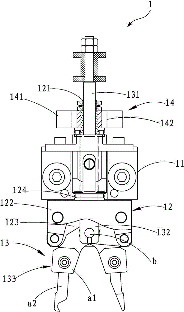
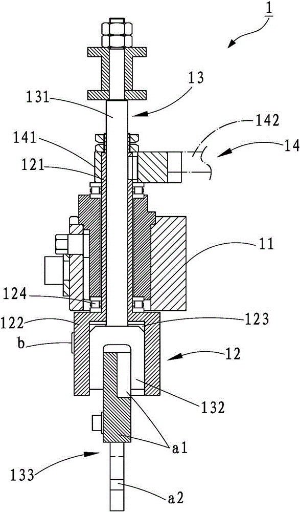
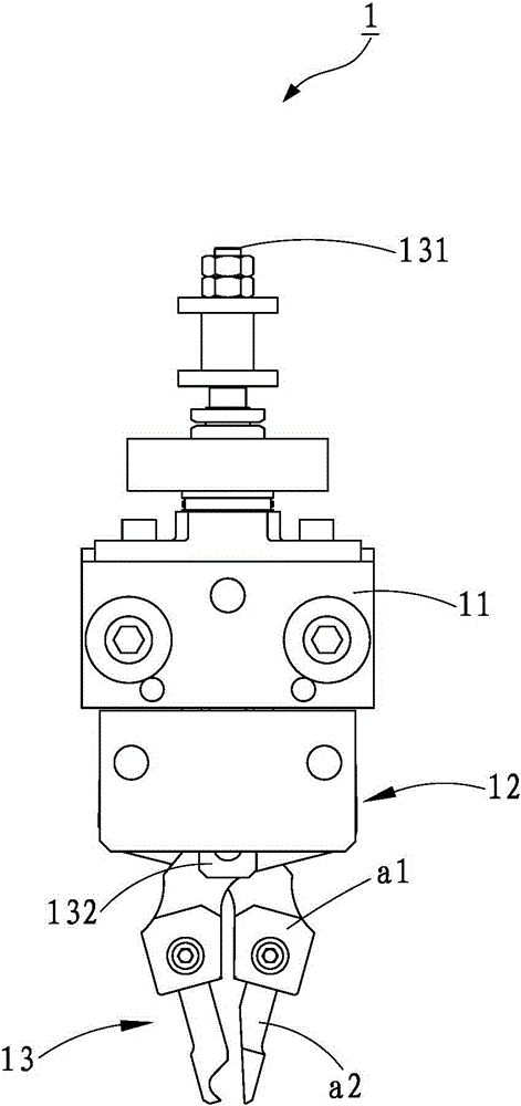
[0028] refer to figure 1 , figure 2 , a preferred embodiment of the clamping device 1 of the forming machine of the present invention, the clamping device 1 is arranged on a forging forming machine, and can be displaced between the forming die and the punching die of the forming machine (not shown in the figure), The clamping device 1 includes a base body 11, a rotating group 12 mounted on the base body 11, a clamping group 13 arranged under the base body 11, and a transmission group 14 that drives the rotating group 12 to rotate. ; Wherein, the rotating group 12 has a hollow sleeve 121 pivotally arranged on the seat body 11, and a rotating seat 122 fixed with the hollow sleeve 121, and the aforementioned rotating seat 122 forms an accommodating space inside 123, and the accommodating space 123 communicates ...


PUM


Abstract

The invention discloses a clamping device for a forming machine. The clamping device comprises a base, a rotary set penetrating through the base, a clamp set arranged below the base, and a transmission set driving the rotary set to rotate; a linkage shaft of the clamp set is connected with a linkage part to drive two clamps connected with the linkage shaft to clamp blank in an opening and closing mode, and meanwhile, a transmission part of the transmission set drives a driving part to rotate so as to synchronously drive the linkage shaft, the rotary base and the clamp set to rotate by 180 degrees in the forward direction / reverse direction, so that the clamping device can be aligned with a position between a forming die and a punch die of the forming machine as needed; in this way, the complexity of forging and punching can be reduced greatly, the addition of unnecessary dies is effectively avoided, and then quick forming is achieved.

Description

technical field [0001] The invention relates to a clamping device of a forming machine. Background technique [0002] The manufacture of most items such as screws, nuts, etc., generally leads the wire directly to the forming machine, and forms a blank of predetermined length through quantitative cutting, and performs forging and stamping operations through various punches and dies of the forming machine. Therefore, in When carrying out the aforementioned processing operations, a fixture is installed between the two dies of the forging forming machine, so that the blank can be clamped to each stage of the manufacturing process in order to perform each stamping and forging operation, so that Complete the consistent forging process; therefore, the setting of the jig in the aforementioned operation flow plays a very important role in the forging operation, which must be carried out during the blank period of each stage. Actions such as clamping, displacement, lifting, etc., so ...

Claims


Application Information

Patent Timeline
Patent Type & Authority Applications(China)
IPC IPC(8): B21J13/10
CPCB21J13/10
Inventor 廖彦荣
Owner 廖彦荣
Why Eureka
Try Eureka