
A row-position ejection mechanism for an injection mold

A technology of injection mold and demoulding mechanism, which is applied in the field of row-position demoulding mechanism, which can solve the problems of lower production efficiency, difficulty of undercutting, cumbersome mold opening action and process, etc., and achieve the effect of improving production efficiency and shortening injection molding cycle

Active Publication Date: 2017-09-19
KUNDA MOLD SHENZHEN
View PDF2 Cites 0 Cited by
  • Summary
  • Abstract
  • Description
  • Claims
  • Application Information

AI Technical Summary

Problems solved by technology

For traditional injection molds, it is necessary to take out the rows from the mold after the injection molding is completed, and then take out the product from the mold. It is very difficult for the product to fall off when the mold is clamped and pressurized, and it is often necessary to add an additional mold opening. Ejecting out the rows, and then demoulding to obtain products, resulting in very cumbersome mold opening actions and processes, and also greatly prolonging the injection molding cycle and reducing production efficiency

Method used


Image

  • A row-position ejection mechanism for an injection mold
  • A row-position ejection mechanism for an injection mold
  • A row-position ejection mechanism for an injection mold

Examples


Embodiment Construction

[0025] In order to make the purpose, technical solutions and advantages of the embodiments of the present invention clearer, the technical solutions in the embodiments of the present invention will be clearly described below in conjunction with the accompanying drawings in the embodiments of the present invention. Obviously, the described embodiments are the Some, but not all, embodiments are invented. Based on the embodiments of the present invention, all other embodiments obtained by persons of ordinary skill in the art without making creative efforts belong to the protection scope of the present invention.

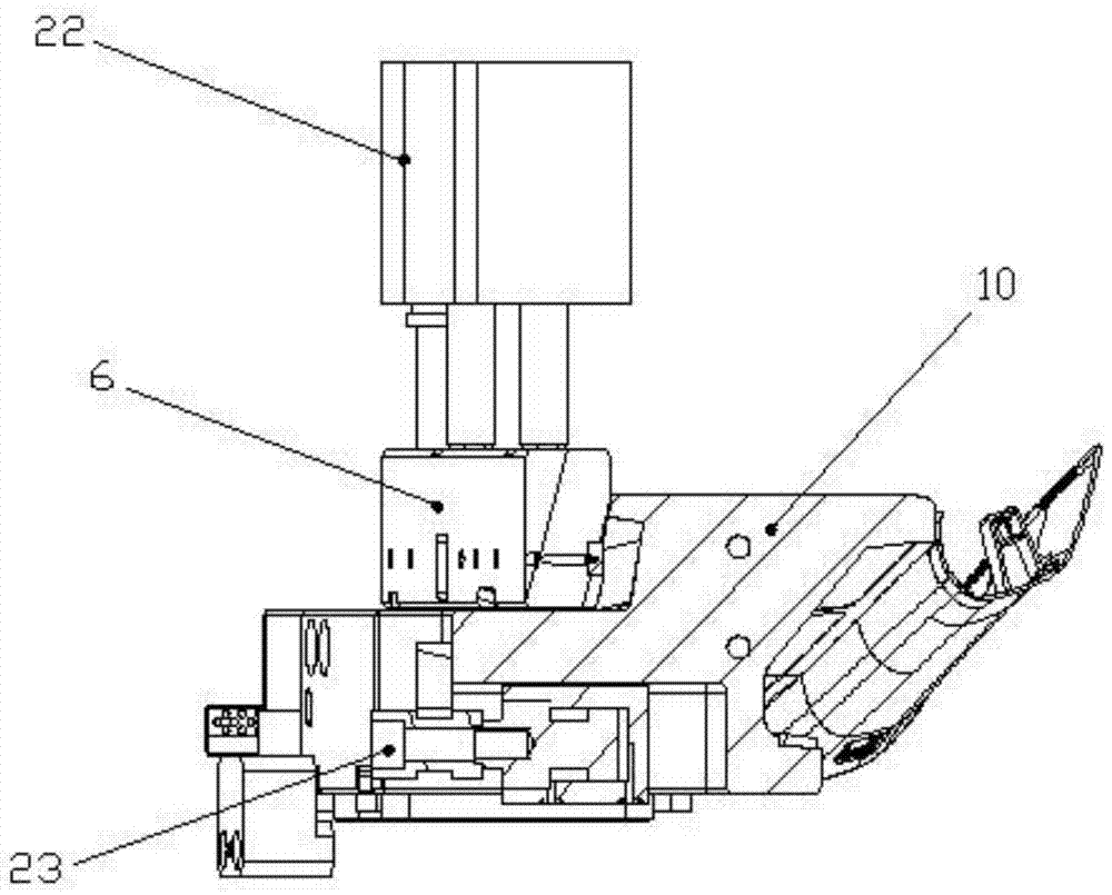
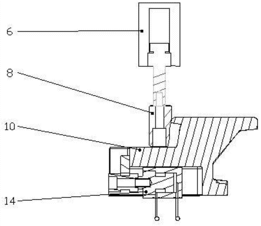
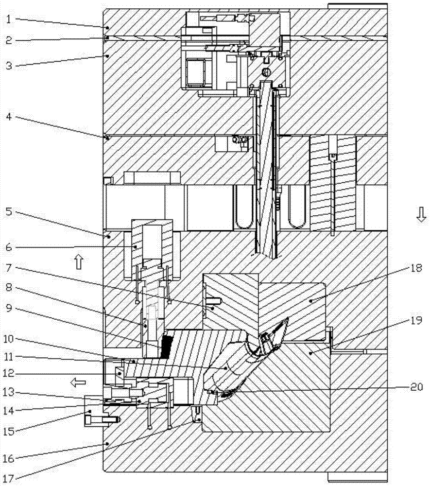
[0026] A row-position demoulding mechanism for an injection mold, the first embodiment of which refers to Figure 1-Figure 2 , which includes row position 10, shovel machine 8, shovel machine oil cylinder 6 and row position oil cylinder 14, wherein in use, row position 10 and the core (including movable mold core 18 and fixed mold core 19) of the injection mold together...


PUM


Abstract

The invention relates to the field of injection moulds, in particular to a slide demoulding mechanism for an in-mould lamination injection mould. The slide demoulding mechanism comprises a slide (10) which forms a mould cavity of the injection mould jointly with a fixed mould core and a movable mould core and is further provided with a heel block (8) used for limiting the position of the slide (10) in the injection mould, a first power mechanism (22) which can drive the heel block (8) to move to relieve limiting of the heel block (8) on the position of the slide (10) in the injection mould and a second power mechanism (23) which can drive the slide (10) to be far away from the mould cavity of the injection mould. According to the slide demoulding mechanism for the in-mould lamination injection mould, the heel block and the slide in the injection mould can be driven by the power mechanisms to be adjusted, so that separation and backoff between the slide and a moulded product can be achieved; compared with the traditional mode that the mould is artificially opened to take the slide out, mechanical operation in the injection mould is achieved, one-time mould opening in the injection process can be reduced, the injection cycle is effectively shortened, and the production efficiency in the injection process is improved.

Description

technical field [0001] The invention relates to the field of injection molds, in particular to a row position demoulding mechanism of an in-mold lamination injection mold. Background technique [0002] Injection molding is a processing method used in the mass production of certain complex-shaped parts. Specifically, it refers to injecting the heated and melted material into the mold cavity, and after cooling and solidifying, a molded product is obtained. Injection mold is a tool for producing plastic products; it is also a tool for giving plastic products complete structure and precise dimensions. Injection molds are generally composed of a moving mold and a fixed mold. The moving mold is installed on the moving template of the injection molding machine, and the fixed mold is installed on the fixed template of the injection molding machine. During injection molding, the movable mold and the fixed mold are closed to form the gating system and the cavity, and the movable mol...

Claims


Application Information

Patent Timeline
Patent Type & Authority Patents(China)
IPC IPC(8): B29C45/40
Inventor 蔡祥力汪智勇周华民于正云
Owner KUNDA MOLD SHENZHEN
Learn More