
A clip-on aero-engine main mounting joint mechanism

A technology of aero-engine and clamping mechanism, which is applied in the construction of power plants, etc., can solve the problems of low installation efficiency of aero-engines, achieve the effects of reducing assembly labor intensity, good practicability, and strong adaptability

Active Publication Date: 2018-03-02
AECC SHENYANG ENGINE RES INST
View PDF6 Cites 0 Cited by
  • Summary
  • Abstract
  • Description
  • Claims
  • Application Information

AI Technical Summary

Problems solved by technology

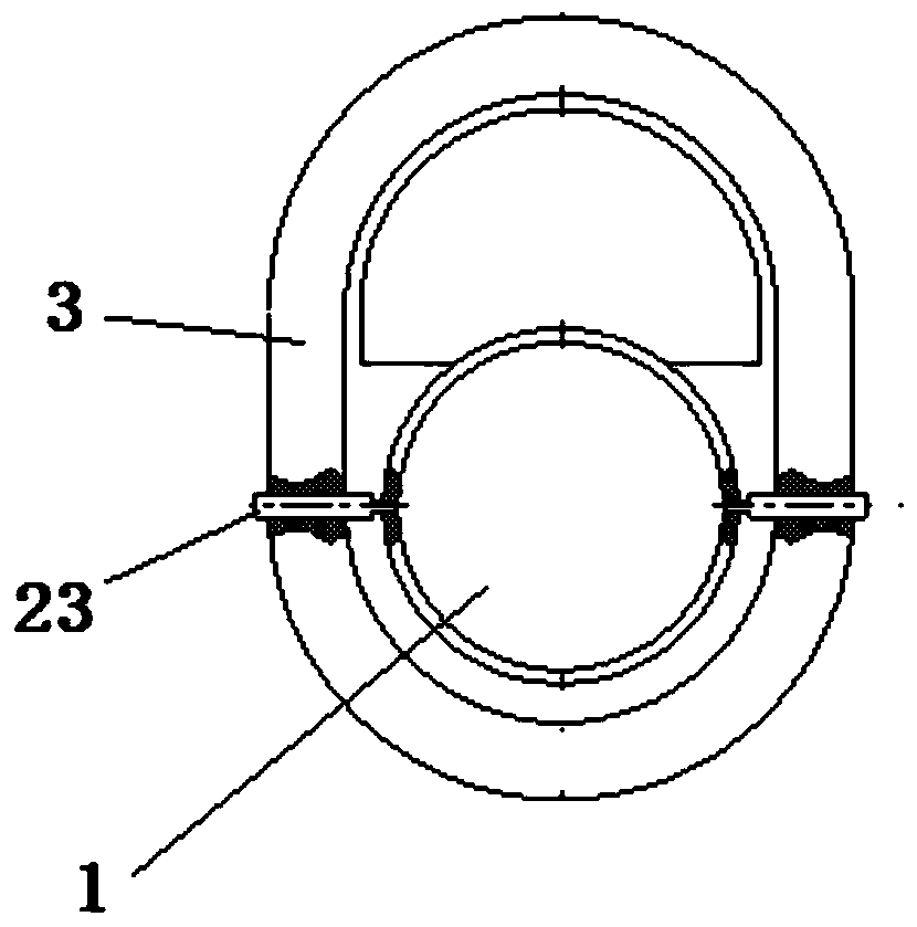
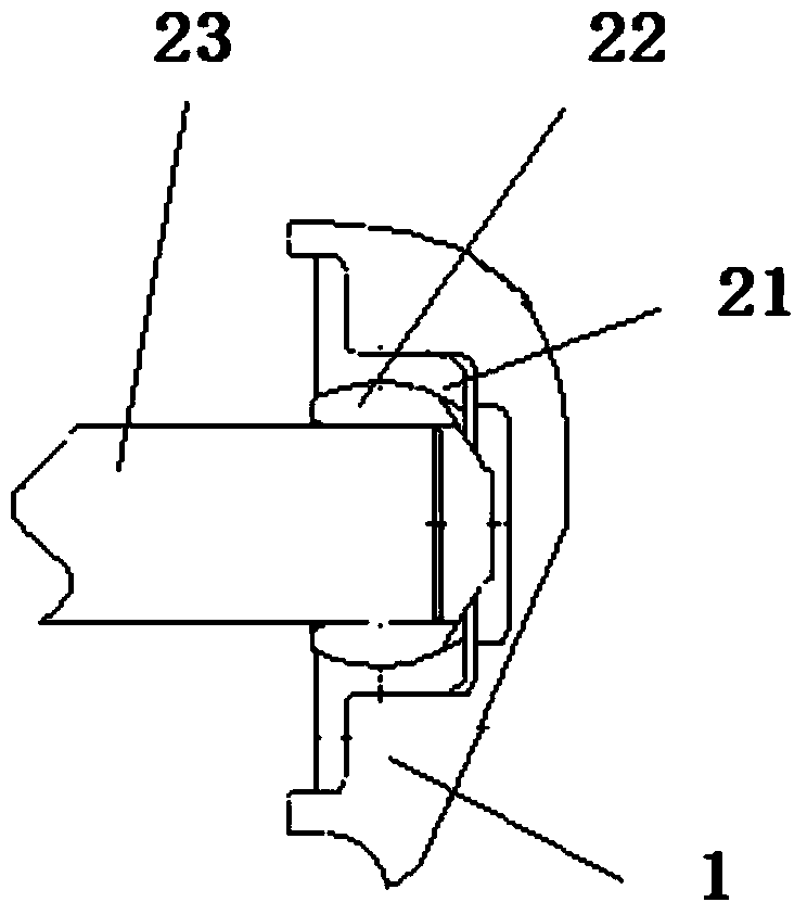
[0008] The purpose of the present invention is to provide a clamping type aero-engine main installation joint mechanism to solve the problem of low installation efficiency of existing aero-engines

Method used


Image

  • A clip-on aero-engine main mounting joint mechanism
  • A clip-on aero-engine main mounting joint mechanism
  • A clip-on aero-engine main mounting joint mechanism

Examples


Embodiment 1

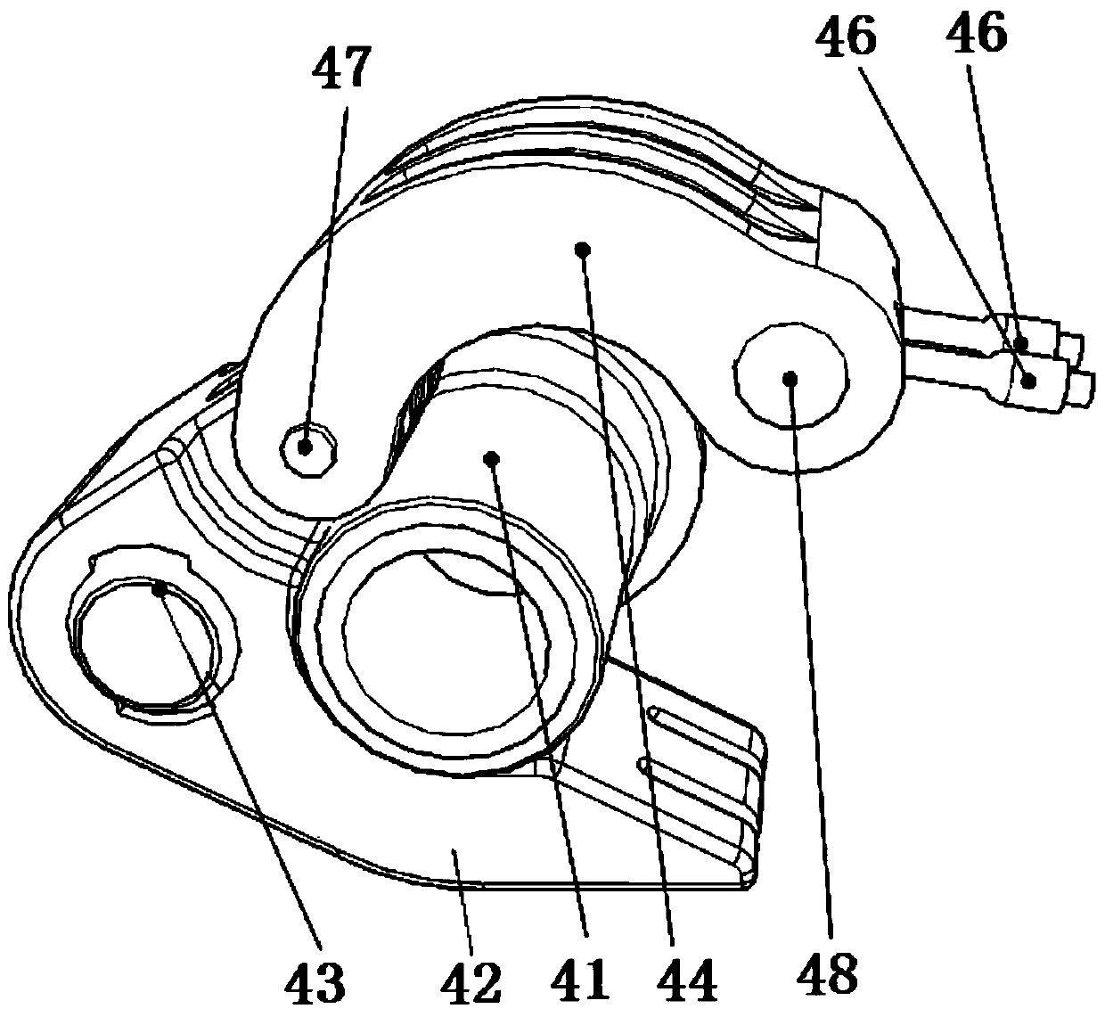
[0039] Especially as image 3 As shown, the clamping mechanism includes a mounting section lower cover 42 and a mounting section upper cover 44 .

[0040] The lower cover 42 of the installation section is bent, and one end ( image 3 middle left end) is provided with a through hole, and the installation joint ball head 43 is movably arranged in the through hole (its internal shape is similar to the ball seat of the prior art), so that the installation joint ball head (43) has a predetermined amount ( Determined by the mounting joint ball head 43 and the through-hole structure) for omni-directional rotation compensation; and, one end of the mounting joint ball head 43 near the engine 1 ( image 3 middle left end) is fixedly connected with the main bearing ring 3 of the aircraft; an end near the engine 1 of the ball joint 43 can be fixedly provided with a shaft (not shown), and is fixedly connected with the main bearing ring 3 of the aircraft by the shaft.

[0041] The mountin...

Embodiment 2

[0044] Especially as Figure 4 As shown, the clamping mechanism also includes a mounting section lower cover 42 and a mounting section upper cover 44 .

[0045] The lower cover 42 of the installation section is bent, and one end ( Figure 4 The left end in the middle) is provided with a through hole, and the fixed pin 45 is fixedly arranged in the through hole, and one end of the fixed pin 45 near the engine 1 is fixedly connected with the main bearing ring (3) of the aircraft.

[0046] The mounting section loam cake 44 is bent shape equally, and one end ( Figure 4 The left end in the center) is hinged on the end with the fixed pin 45 of the lower cover 42 of the installation section through the first rotating shaft 47.

[0047] One end of the thrust pin 41 close to the engine 1 is fixedly connected with the installation joint ball 43, and the installation joint ball 43 is movably installed in the installation joint ball seat of the engine 1 (the installation joint ball seat ...


PUM


Abstract

The invention relates to the field of aero-engine design, in particular to a clip-type aero-engine main installation joint mechanism to solve the problem of low installation efficiency of the existing aero-engine. The clamping type aero-engine main mounting joint mechanism includes: two thrust pins, which are respectively set on the main load-bearing casings on the horizontal sides of the engine; two clamping mechanisms, which are respectively set on the main load-bearing rings on the horizontal sides of the aircraft , the clamping mechanism on each side is used to fix and clamp the thrust pin on the corresponding side, and the clamped engine is at a predetermined installation position. In addition, the engine at the predetermined installation position has a predetermined amount of omni-directional rotation compensation. In the engine main mounting joint mechanism of the present invention, the thrust pin protrudes outside the engine contour, thereby avoiding the difficulty of inserting the thrust pin into the mounting hole of a small gap, so that the mounting holes of the aero-engine and the aircraft can be accurately aligned, reducing assembly labor strength.

Description

technical field [0001] The invention relates to the field of aero-engine design, in particular to a clip-type aero-engine main mounting joint mechanism. Background technique [0002] The installation section is the connection between the aero-engine and the aircraft, and it is divided into the main installation section and the auxiliary installation section. The main installation section bears the main load of the aero-engine, is an important component that transmits the thrust of the aero-engine to the aircraft, and is also the main positioning mechanism of the aero-engine on the aircraft. During the flight of the aircraft, various loads are transmitted to the engine through the main mounting joint, so the mounting joint must have sufficient rigidity, strength and high reliability. [0003] The aero engine is the core component of the aircraft, and the engine needs to be maintained regularly during the use of the aircraft. The design of the main installation section of th...

Claims


Application Information

Patent Timeline
Patent Type & Authority Patents(China)
IPC IPC(8): B64D27/26B64D27/40
Inventor 刘旭阳徐雪田大可张德志怀时卫
Owner AECC SHENYANG ENGINE RES INST
Learn More