Needle dial adjusting structure of double-faced knitting machine

A technology of adjusting structure and double-sided machine, applied in knitting, weft knitting, textile and papermaking, etc., can solve the problems of affecting the rigidity of the whole machine, unable to tighten the screws too tightly, reducing the assembly accuracy of the whole machine, etc.

Active Publication Date: 2015-12-30
JINJIANG HONGJI MACHINERY
View PDF7 Cites 1 Cited by
  • Summary
  • Abstract
  • Description
  • Claims
  • Application Information

AI Technical Summary

Problems solved by technology

The biggest defect of this method is that there is a certain distance between the fastening point and the adjustment support point. On the one hand, due to the effect of stress deformation, when the dial is in a fixed state, the flatness of the end face of the dial has a certain influence, thereby reducing the The assembly accuracy of the whole machine; on the other hand, in order not to affect the assembly accuracy as much as possible, the installer cannot lock the fastening screw 12 too tightly, which affects the rigidity of the whole machine

Method used


Image

  • Needle dial adjusting structure of double-faced knitting machine
  • Needle dial adjusting structure of double-faced knitting machine
  • Needle dial adjusting structure of double-faced knitting machine

Examples


Embodiment 1

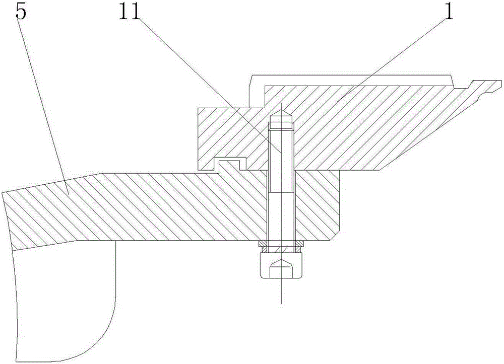
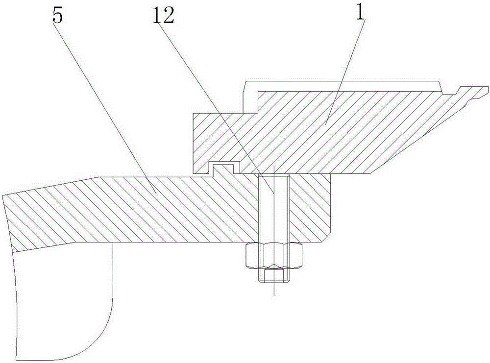
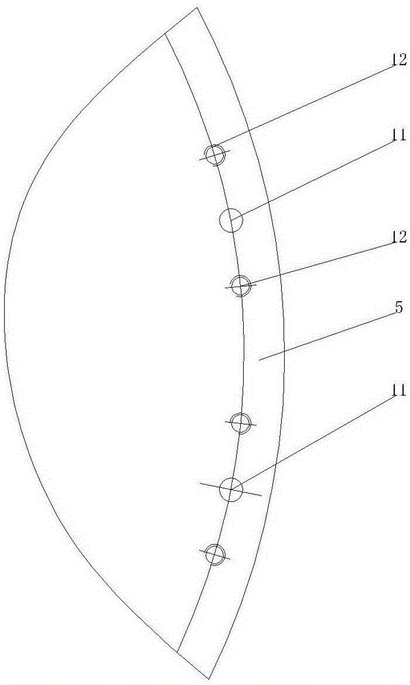
[0017] Such as Figure 4 , Figure 5 , Image 6 , Figure 7 As shown, the dial adjustment structure of double-sided machine includes locking screw 2, hollow screw cover 3 set on locking screw 2, locking block set under hollow screw cover 3 and set on locking screw 2 4. The locking screw 2 passes through the support plate 5 and is locked on the upper dial 1, the hollow screw cover 3 is set in the through hole 51 of the support plate 5, and the hollow screw cover 3 and the through hole of the support plate 5 Threaded connection, the bottom of the hollow screw jacket 3 is provided with a "ten"-shaped groove 31, and the upper end of the locking block 4 is provided with a "ten"-shaped convex key 41 to match the "ten"-shaped groove 31. The "ten" shaped protruding key 41 is inserted into the "ten" shaped groove 31 . The hollow screw jacket 3 is matched with the locking block 4 in the axial direction, the locking block 4 is an inverted T-shaped structure, and the lower part is pro...

Embodiment 2

[0019] Such as Figure 4 , Figure 5 , Image 6 , Figure 7 As shown, the patent of the present invention cancels all the stop screws 12 installed on both sides of the locking screw 2, and a hollow screw cover 3 is installed around each locking screw 2. The hollow screw jacket 3 is hollow, and a corresponding locking screw is installed, and the outside is connected with the threaded support disc at the bottom of the upper needle disc. At the bottom of the hollow screw jacket 3, a "ten" shaped concave keyway 31 is manufactured, and the "cross" shaped concave keyway 31 must be installed on the hexagonal locking block 4 below the screw jacket. The key 41 is matched, and in the axial direction, the installation position of the hollow screw sleeve 3 should be kept at the bottom and the hexagonal locking block equipped with the "ten"-shaped convex key to maintain a gap, and fully extend the support plate at the top of the upper plane. In this way, when all the hexagonal locking...


PUM


Abstract

The invention relates to the field of double-faced knitting machines of circular knitting machines and particularly relates to a needle dial adjusting structure of the double-faced knitting machine. The needle dial adjusting structure comprises locking screws, hollow screw outer sleeves which sleeve the locking screws, and locking blocks which are arranged under the hollow screw outer sleeves and sleeve the locking screws, wherein the locking screws penetrate through a supporting disc to be locked on a needle dial; a through hole of the supporting disc sleeves the hollow screw outer sleeves; the hollow screw outer sleeves are in threaded connection with the through hole of the supporting disc; a cross-shaped groove is formed in the bottom of each hollow thread outer sleeve; the upper end of each locking block is provided with a cross-shaped convex key which is matched with the corresponding cross-shaped groove; the cross-shaped convex keys are inserted into the cross-shaped grooves. With the adoption of the structure, the structure guarantees a locking function of the locking screws and the flatness of the needle dial is convenient and easy to adjust; the rigidity of a whole machine is guaranteed, and all the locking screws only bear pure tension; all the locking blocks are tightly combined with the screw outer sleeves and an upper needle dial is tightly connected with the supporting disc; any waveform-shaped stress deformation is not generated and the installation intensity of the whole machine is higher.

Description

technical field [0001] The invention relates to the field of circular knitting double-sided knitting machines, in particular to the adjusting structure of the needle disc of the double-sided machine. Background technique [0002] For a long time, in the traditional technology, in the double-sided machine series of large circular knitting machines, the fixed installation and adjustment methods of the upper dial are relatively rough. As we all know, the upper dial 1 needs to correct its radial runout and end face runout before operation. Such as figure 1 , figure 2 , image 3 As shown, the fixing and adjustment method of the upper dial 1 depends on a circle of fastening screws 11, and at the same time, a pair of stop screws 12 are distributed on both sides of each fastening screw 11 for adjusting the upper dial 1. Circle beating. While adjusting the stop screw 12, tighten all fastening screws 11. The biggest defect of this method is that there is a certain distance betw...

Claims


Application Information

Patent Timeline
Patent Type & Authority Applications(China)
IPC IPC(8): D04B15/18D04B15/00
Inventor 苏志远曾志明陈财宝易新生
Owner JINJIANG HONGJI MACHINERY
Why Eureka
Try Eureka