Ceiling fan flange and ceiling fan provided with same

A ceiling fan flange and flange technology, applied to components of pumping devices for elastic fluids, non-variable pumps, pump devices, etc., can solve the unavoidable problems of motor shafts, etc., to improve production efficiency and reliability Sexuality, improvement of fixed structure, and the effect of enhancing market competitiveness

Active Publication Date: 2015-12-30
GUANGDONG SHUNDE LIANGCI ELECTRIC CO LTD
View PDF8 Cites 22 Cited by
  • Summary
  • Abstract
  • Description
  • Claims
  • Application Information

AI Technical Summary

Problems solved by technology

However, during use, it is still difficult for the above-mentioned fixed

Method used


Image

  • Ceiling fan flange and ceiling fan provided with same
  • Ceiling fan flange and ceiling fan provided with same
  • Ceiling fan flange and ceiling fan provided with same

Examples


Embodiment 1

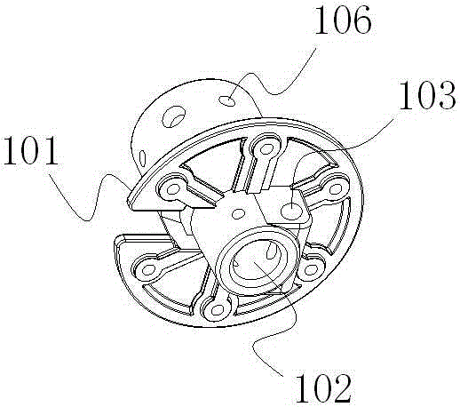
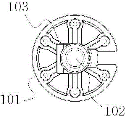
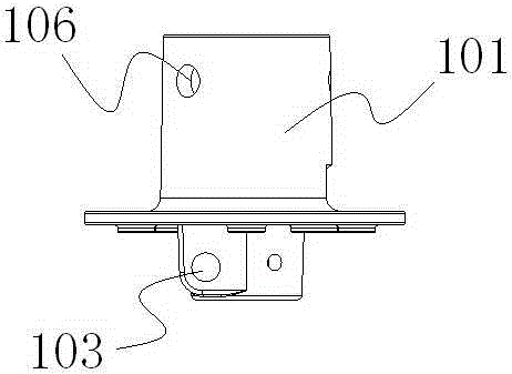
[0028] Such as Figure 1~3 As shown, the ceiling fan flange of this embodiment includes a flange body 101, and the flange body 101 is provided with a screw hole 102. The key point is that the lower part of the flange body 101 is provided with a through hole 103 orthogonal to the screw hole 102, Part of the through hole 103 communicates with the screw hole 102; the through hole 103 is fixedly equipped with a fixed pin 104, and the side of the fixed pin 104 is provided with an anti-rotation plane 105, and the anti-rotation plane 105 of the fixed pin 104 A part is located in the direction of the screw hole 102 and located in the screw hole 102 . The fixed pin 104 is secured by an "R" shaped spring 108 passing through the end of the fixed pin 104 .

[0029] Such as Figure 4~7 As shown, the ceiling fan of this embodiment includes a motor shaft 2, a motor 3, fan blades and the above-mentioned flange 1, the motor 3 is mounted on the motor shaft 2, the fan blades are mounted on the...


PUM


Abstract

The invention aims to provide a ceiling fan flange which is convenient to fix and reliable and a ceiling fan provided with the flange. The ceiling fan flange comprises a flange body, and a screw hole is formed in the flange body. The ceiling fan flange is characterized in that a through hole is formed in the flange body, and a part of the through hole is communicated with the screw hole; a fixing pin is fixedly mounted in the through hole, a rotation preventing plane is arranged at the side part of the fixing pin and faces the screw hole, and part of the rotation preventing plane is located in the screw hole. The ceiling fan comprises a motor shaft, a motor, fan blades and the flange, the motor is mounted on the motor shaft, the fan blades are mounted on the motor, external threads are formed in the upper part of the motor shaft, and the motor shaft extends into the screw hole in the flange and is connected and fixed with the flange in a screw-thread fit manner. More importantly, a fixing plane is arranged at the side part of the upper part of the motor shaft and is opposite to the rotation preventing plane of the fixing pin.

Description

technical field [0001] The invention belongs to the technical field of electric appliance manufacturing, and in particular relates to a ceiling fan flange and a ceiling fan with the flange. Background technique [0002] A ceiling fan generally includes a flange, a motor shaft, a motor and fan blades, wherein the motor and the fan blades are all installed on the motor shaft, and the motor shaft is connected to the suspension rod by the flange, and is fixedly installed on the ceiling. Specifically, the motor shaft is fixed with the flange by thread fit. In order to prevent the motor shaft from rotating relative to the flange during the working process of the fan and causing the motor shaft to fail, a fixing pin is installed on the side of the flange to fix the fan. The pin passes through the flange but the front end of the fixed pin is pressed against the motor shaft, and the motor shaft is prevented from rotating by the pressure applied by the fixed pin to the side of the mot...

Claims


Application Information

Patent Timeline
IPC IPC(8): F04D29/00F04D25/08F04D29/60
Inventor 阮国永
Owner GUANGDONG SHUNDE LIANGCI ELECTRIC CO LTD
Why Eureka
Try Eureka