Supercharge Your Innovation With Domain-Expert AI Agents!

Piston plane self-sealing structure for hydraulic cylinder

A technology of self-sealing structure and hydraulic cylinder, which is applied in the direction of fluid pressure actuating device, etc., can solve the problems of aging of seals, low roughness of cylinder inner hole, unreasonable selection of seals, etc., and achieve good sealing performance

Inactive Publication Date: 2015-12-30
JIANGSU HENGLI HYDRAULIC
View PDF6 Cites 0 Cited by
  • Summary
  • Abstract
  • Description
  • Claims
  • Application Information

AI Technical Summary

Problems solved by technology

[0003] 1. Oil cylinder processing problems, such as the roughness of the inner hole of the cylinder is too low, the cylindricality of the inner hole is too low, and the groove finish on the piston is poor
[0004] 2. Unreasonable selection of seals, or aging and failure of seals
[0005] 3. Problems with the use of the oil cylinder, the system pressure is too high, causing the oil cylinder to expand, and the load is too heavy, causing the inner hole of the oil cylinder to be strained
[0007] In the hydraulic cylinder, the sealing ring at the leak in 2 is often damaged due to the actual working pressure being too high, causing leakage in the cylinder.

Method used


Image

  • Piston plane self-sealing structure for hydraulic cylinder
  • Piston plane self-sealing structure for hydraulic cylinder
  • Piston plane self-sealing structure for hydraulic cylinder

Examples


Embodiment Construction

[0020] The following will clearly and completely describe the technical solutions in the embodiments of the present invention. Obviously, the described embodiments are only some of the embodiments of the present invention, rather than all the embodiments. Based on the embodiments of the present invention, all other embodiments obtained by persons of ordinary skill in the art without making creative efforts belong to the protection scope of the present invention.

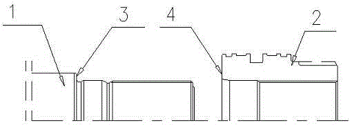
[0021] see figure 1 , the embodiment of the present invention includes:

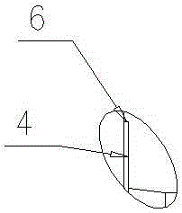
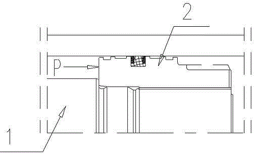
[0022] A hydraulic cylinder piston planar self-sealing structure, comprising: a piston rod 1 and a piston 2, one end surface of the piston rod 1 is set as a D surface 3, and one end surface of the piston 2 is set as an E surface 4.

[0023] In the prior art, a sealing ring is added between the piston rod 1 and the piston 2. In the present invention, the sealing ring is canceled, and only the D surface 3 of the piston rod 1 and the E surface 4 ...


PUM


Abstract

The invention discloses a piston plane self-sealing structure for a hydraulic cylinder. A side D and a side E are contacted with each other to form a closed ring, wherein the finish degree of the side D ranges from 3.0 to 3.3, and the perpendicularity with a threaded side of a piston rod is larger than or equal to 0.05; the finish degree of the side E ranges from 1.5 to 1.7, and the perpendicularity with the threaded side of the piston is larger than or equal to 0.05. With adoption of the scheme, the sealing effect can be realized finally only through certain plastic deformation generated by the side D of the piston rod and the side E of the piston due to pre-tightening force after the piston is tightened, a system realizing sealing merely through surface contact of workpieces is formed, sealing elements are not needed, and the sealing has the characteristics that the higher the pressure is, the larger the pressing force of the sealing original pieces on the contact surfaces is and the better the sealing performance is.

Description

technical field [0001] The invention relates to the field of hydraulic oil cylinder piston sealing, in particular to a hydraulic oil cylinder piston plane self-sealing structure. Background technique [0002] Leakage in the cylinder is one of the most common failures of hydraulic cylinders. There are many reasons for internal leakage: [0003] 1. Cylinder processing problems, such as the roughness of the inner hole of the cylinder is too low, the cylindricality of the inner hole is too low, and the groove finish on the piston is poor. [0004] 2. Unreasonable selection of seals, or aging and failure of seals. [0005] 3. Problems with the use of the oil cylinder. The high system pressure causes the oil cylinder to swell, and the load is too heavy, which causes the inner hole of the oil cylinder to be strained. [0006] Generally, when designing an ordinary hydraulic cylinder, a sealing ring must be designed on the piston to prevent internal leakage during the working proc...

Claims


Application Information

Patent Timeline
Patent Type & Authority Applications(China)
IPC IPC(8): F15B15/20
Inventor 汪立平
Owner JIANGSU HENGLI HYDRAULIC
Features
  • R&D
  • Intellectual Property
  • Life Sciences
  • Materials
  • Tech Scout
  • Unparalleled Data Quality
  • Higher Quality Content
  • 60% Fewer Hallucinations
Learn More