
Coupling

A technology of shaft couplings and shaft sleeves, which is applied in the direction of shaft couplings, rigid shaft couplings, and mechanical equipment, and can solve problems such as large impact, reduced service life of couplings, high requirements for equipment manufacturing, and high installation accuracy. To achieve the effect of smooth transmission

Inactive Publication Date: 2015-12-30
BEIJING JINGCHENG RUIXINCHANGCAI ENG TECH
View PDF7 Cites 0 Cited by
  • Summary
  • Abstract
  • Description
  • Claims
  • Application Information

AI Technical Summary

Problems solved by technology

[0002] At present, in the domestic rod and wire production line, drum gear couplings, rigid couplings or diaphragm couplings are mainly used to connect the transmission shafts of cooling beds, flying shears and other equipment; electric stepping eccentric wheel cooling beds, low speed When the shaft is rotating, the direction of the load changes periodically. At this stage, drum-shaped gear couplings or rigid couplings are generally used; due to the existence of backlash in the drum-shaped gear couplings, there will be abnormal noises when the load direction changes, resulting in noise , while reducing the service life of the coupling; since the rigid coupling has no compensation function, it has high requirements for equipment manufacturing and installation accuracy, and it is difficult to assemble; the start-stop flying shear adopts a drum-shaped tooth When stopping, vibration and noise are generated due to the backlash of the drum-shaped gear coupling; when the diaphragm coupling is used, the diaphragm is easily damaged due to the large impact when the flying shear starts and stops

Method used


Image

  • Coupling
  • Coupling
  • Coupling

Examples


Embodiment Construction

[0026] In order to make the technical problems, technical solutions and advantages to be solved by the present invention clearer, the following will describe in detail with reference to the drawings and specific embodiments.

[0027] Aiming at the problem that the transmission of the existing shaft coupling is not stable and the noise is easy to be generated during operation, the invention provides a shaft coupling.

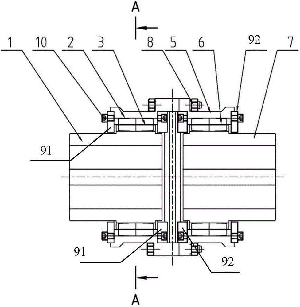
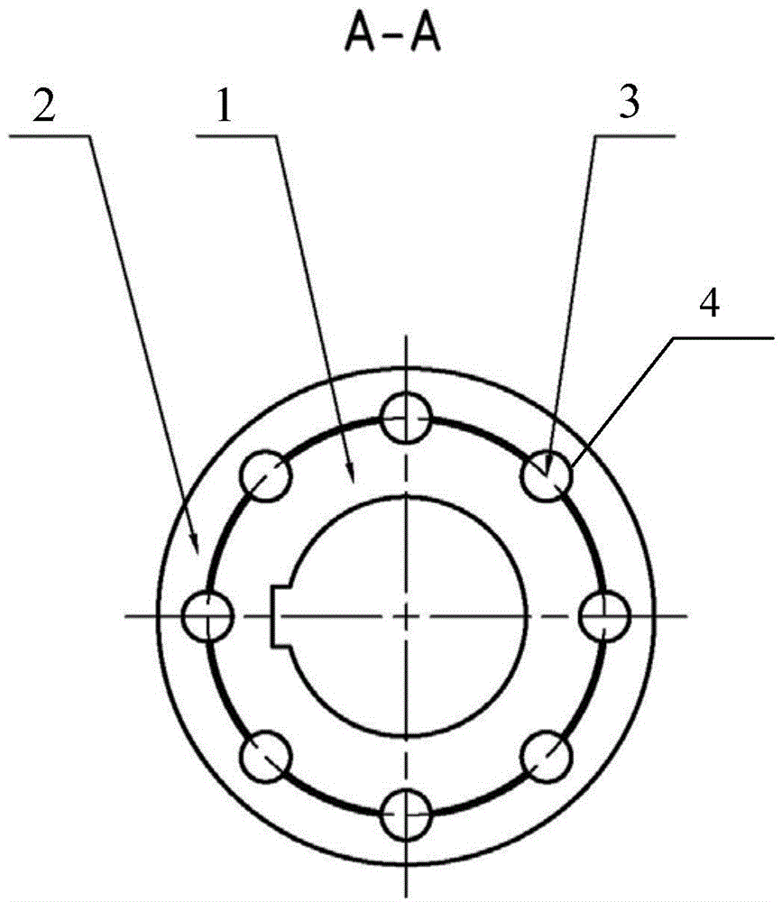
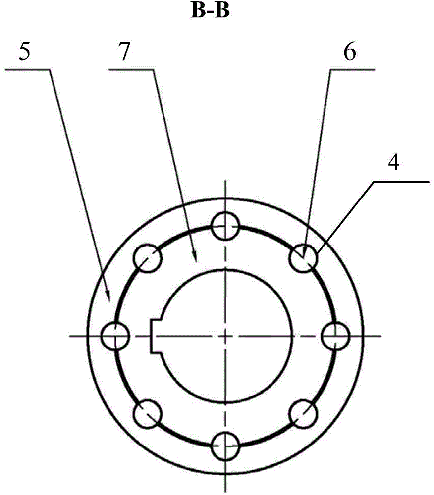
[0028] Such as figure 1 , figure 2 As shown, the embodiment of the present invention provides a coupling, which is applied to the transmission shaft connection, including: the first sleeve 1 connected with the first transmission shaft, and arranged along the circumferential direction of the outer surface of the first sleeve 1 There are a plurality of installation holes 4, and each installation hole 4 is provided with a first arc roller 3; the first hub 2 sleeved outside the first arc roller 3; as image 3 As shown, and the second shaft sleeve 7 connected with ...


PUM


Abstract

The invention provides a coupling applied to transmission shaft connection. The coupling comprises a first shaft sleeve, a first hub, a second shaft sleeve and a second hub, wherein the first shaft sleeve is connected with a first transmission shaft, a plurality of installation holes are formed in the circumferential direction of the outer surface of the first shaft sleeve, and each installation hole is internally provided with a first arc-shaped roller; the first arc-shaped rollers are sleeved with the first hub; the second shaft sleeve is connected with a second transmission shaft, a plurality of installation holes are formed in the circumferential direction of the outer surface of the second shaft sleeve, and each installation hole is internally provided with a second arc-shaped roller; the second arc-shaped rollers are sleeved with the second hub, and the second hub is connected with the first hub. Micro gaps exist between the arc-shaped rollers and the shaft sleeves and between the arc-shaped rollers and the hubs in the coupling so that shaft transmission can be stable, environment friendliness is achieved, and noise does not exist. Besides, the coupling has the performance of slightly compensating for relative deviation of the two shafts and also has certain buffering and shock-absorbing effects.

Description

technical field [0001] The invention relates to transmission shaft connection technology, in particular to a coupling. Background technique [0002] At present, in the domestic rod and wire production line, drum gear couplings, rigid couplings or diaphragm couplings are mainly used to connect the transmission shafts of cooling beds, flying shears and other equipment; electric stepping eccentric wheel cooling beds, low speed When the shaft is rotating, the direction of the load changes periodically. At this stage, drum-shaped gear couplings or rigid couplings are generally used; due to the existence of backlash in the drum-shaped gear couplings, there will be abnormal noises when the load direction changes, resulting in noise , while reducing the service life of the coupling; since the rigid coupling has no compensation function, it has high requirements for equipment manufacturing and installation accuracy, and it is difficult to assemble; the start-stop flying shear adopts ...

Claims


Application Information

Patent Timeline
Patent Type & Authority Applications(China)
IPC IPC(8): F16D1/033
Inventor 丁玉龙杨国际王东
Owner BEIJING JINGCHENG RUIXINCHANGCAI ENG TECH
Learn More