Light splitting and combining device and projection optical system

A technology of projection optical system and optical device, which is applied in the field of optics and can solve problems such as back focal length

Active Publication Date: 2015-12-30
APPOTRONICS CORP LTD
View PDF5 Cites 10 Cited by
  • Summary
  • Abstract
  • Description
  • Claims
  • Application Information

AI Technical Summary

Problems solved by technology

[0006] In view of this, the present invention provides a light splitting and combining device

Method used


Image

  • Light splitting and combining device and projection optical system
  • Light splitting and combining device and projection optical system
  • Light splitting and combining device and projection optical system

Examples


Embodiment 1

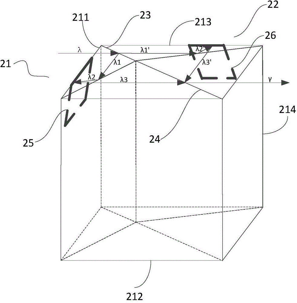
[0134] This embodiment provides a light splitting and combining device, such as figure 2 As shown, is a perspective view of the light splitting and combining device provided in this embodiment. The light splitting and combining device includes the first TIR21 and the second TIR22 that are adjacently arranged, and the first optical element 23 that is arranged on a part of the surface adjacent to the first TIR21 and the second TIR22 and the other that is arranged on the adjacent part of the first TIR21 and the second TIR22. A portion of the surface of the second optical element 24 . in:

[0135] The first TIR 21 includes a first prism 211 and a second prism 212 disposed adjacently. The surface adjoining the first prism 211 and the second prism 212 is a total reflection surface that totally reflects light rays whose incident crossing is greater than the first angle threshold, such as by setting air between the adjoining surfaces of the first prism 211 and the second prism 212 ...

Embodiment 2

[0159] This embodiment provides another light splitting and combining device, such as Figure 5 As shown, is a perspective view of the light splitting and combining device provided in this embodiment. The difference between the light splitting and combining device and the light splitting and combining device described in Embodiment 1 is that the first prism, the second prism included in the first TIR and the third prism and the fourth prism included in the second TIR are deformed, so that The incident angle α of the incident light λ incident on the first optical element 23 is less than 45 degrees. The details are as follows:

[0160] The light splitting and combining device includes the first TIR51 and the second TIR52 that are adjacently arranged, and the first optical element 23 that is arranged on a part of the surface adjacent to the first TIR51 and the second TIR52 and the other that is arranged on the adjacent part of the first TIR51 and the second TIR52. A portion of ...

Embodiment 3

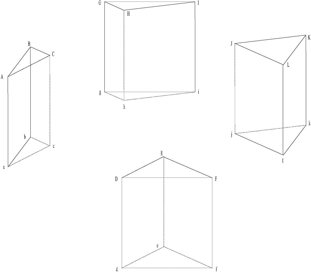
[0170] This embodiment provides another light splitting and combining device, such as Figure 7 As shown, is a perspective view of the light splitting and combining device provided in this embodiment. The difference between the light splitting and combining device and the light splitting and combining device described in Embodiment 2 is that, in order to make the incident light vertically incident on the light splitting and combining device, and make the outgoing light perpendicular to the light splitting and combining device, the light splitting and combining device also includes The fifth prism 75 and the sixth prism 76 . in:

[0171] The fifth prism 75 is arranged adjacent to the first surface of the first prism 511, and the fifth prism 75 includes a first surface adjacent to the first surface of the first prism 511, a second prism perpendicular to the incident light and used for incident light surface. The fifth prism 75 may be a prism of any shape including the first s...


PUM

PropertyMeasurementUnit
Angle of incidenceaaaaaaaaaa

Abstract

The present invention relates to the technical field of optical technology and provides a light splitting and combining device and projection optical system. The light splitting and combining device comprises a first TIR and a second TIR which is adjacent to the first TIR. One part of the adjacent surface of the first TIR and the second TIR is provided with a first optical element, the other part is provided with a second optical element, wherein the first optical element is used for splitting the incident light beam emitted to the light splitting and combining device into a beam transmitted along a first optical channel and a beam transmitted along a second optical channel, and the second optical element is used for combining the beam emitted by a first spatial light modulator and the beam emitted by a second spatial light modulator into a beam. By using the light splitting and combining device provided by the invention, the back focus of the projection system can be shortened greatly, thus the structure is more compact, and thus the volume of the projection system is reduced.

Description

technical field [0001] The invention relates to the field of optical technology, more specifically, to a light source system and a projection optical system. Background technique [0002] Existing projection optical systems include a single-chip DMD (Digital MicroMirror Device, digital micromirror device) projection optical system, a two-chip DMD projection optical system, and a three-chip DMD projection optical system. The two-chip DMD has become an ideal choice for the mid-end market in the projection field because of the balance between cost and light efficiency. [0003] The structure of the existing two-piece DMD projection optical system is as follows: figure 1 As shown, the projection optical system includes a light source 101, a collection lens 102, a color wheel 103, a uniform light device 104, an optical relay device 105, a TIR prism 106, a Philips (Philips) prism 107, a first DMD chip 108a, a second DMD Chip 108b and projection lens 109 . in: [0004] The firs...

Claims


Application Information

Patent Timeline
IPC IPC(8): G02B27/10G02B27/18G03B21/20
Inventor 王则钦郭祖强
Owner APPOTRONICS CORP LTD
Why Eureka
Try Eureka