Image display apparatus
a technology of image display and display device, which is applied in the field of image display device, can solve the problems of inability to reduce the size of the unit, deterioration of the optical performance of the reflective light modulator, etc., and achieve the effect of reducing the siz
- Summary
- Abstract
- Description
- Claims
- Application Information
AI Technical Summary
Benefits of technology
Problems solved by technology
Method used
Image
Examples
first embodiment
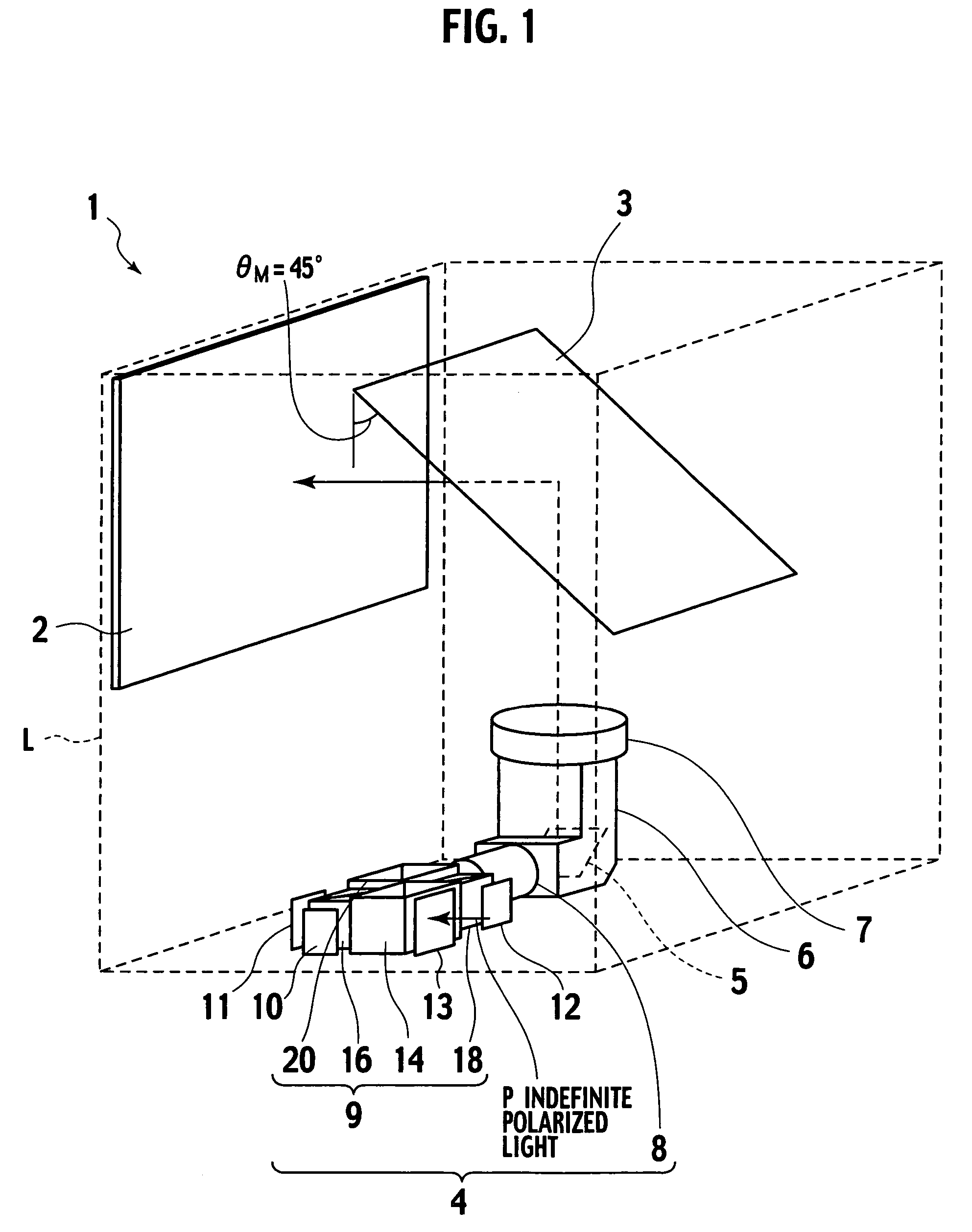
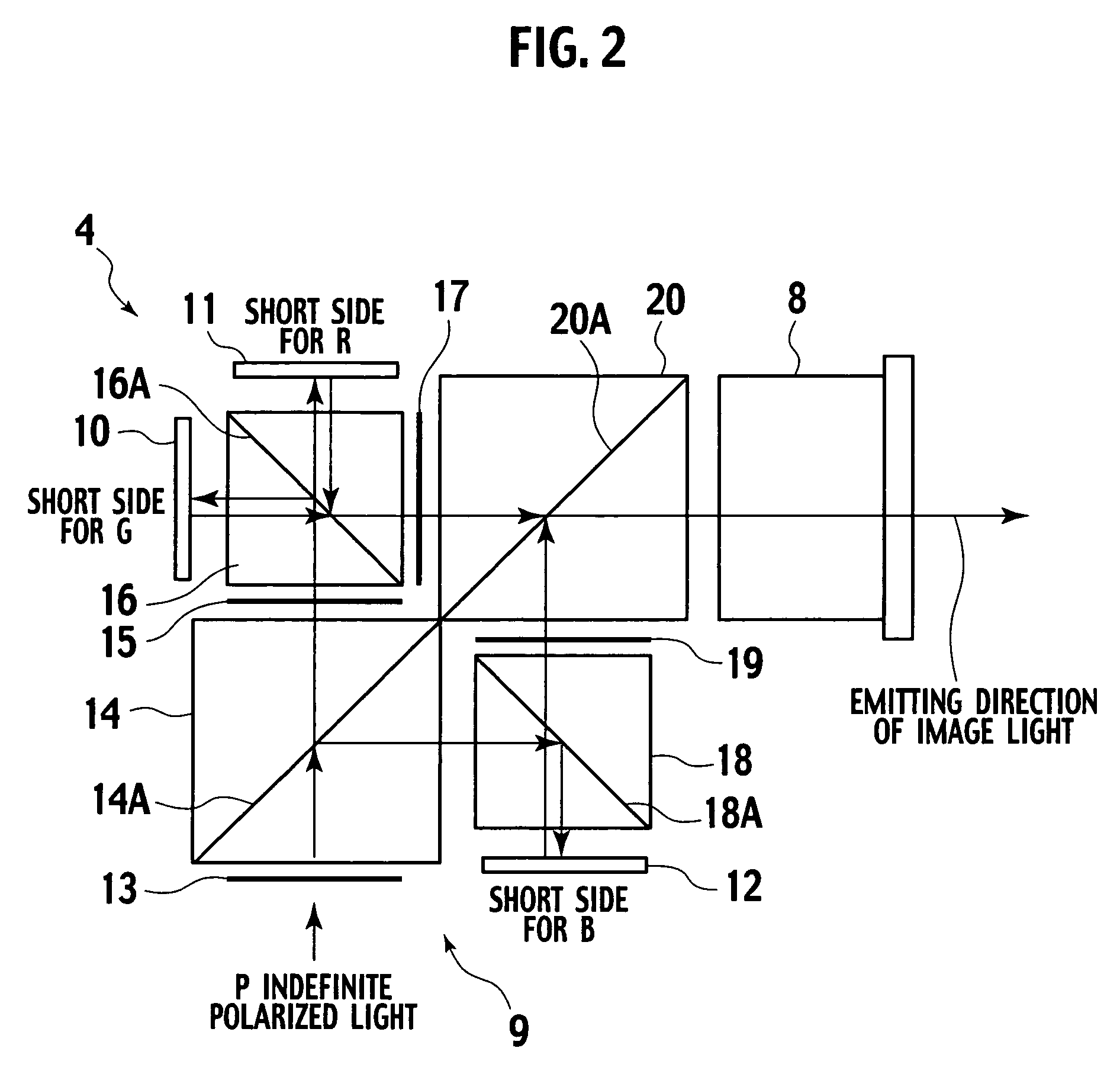
[0022]FIG. 1 is a perspective view showing a first embodiment of an image display apparatus according to the present invention. FIG. 2 is a view illustrating a configuration of a liquid crystal projector. FIG. 3 is a view illustrating an arrangement of a reflecting mirror according to the first embodiment.
[0023]In FIG. 1, constituent components accommodated in a box member L are indicated by solid lines, and a box member L is indicated by broken lines for the convenience's sake.
[0024]As shown in FIG. 1, an image display apparatus 1 according to the first embodiment of the present invention comprises: a plane mirror 3 arranged at an angle θM=45° with respect to a screen 2; a liquid crystal projector 4 arranged between the screen 2 and the plane mirror 3; a reflecting mirror 5 which reflects image light emitted from the liquid crystal projector 4; a light guiding tube 6 in which the reflecting mirror 5 is accommodated; and a projection lens 7 which projects the image light reflected b...
second embodiment
[0053]A second embodiment according to the present invention will now be described with reference to FIGS. 4 and 5.
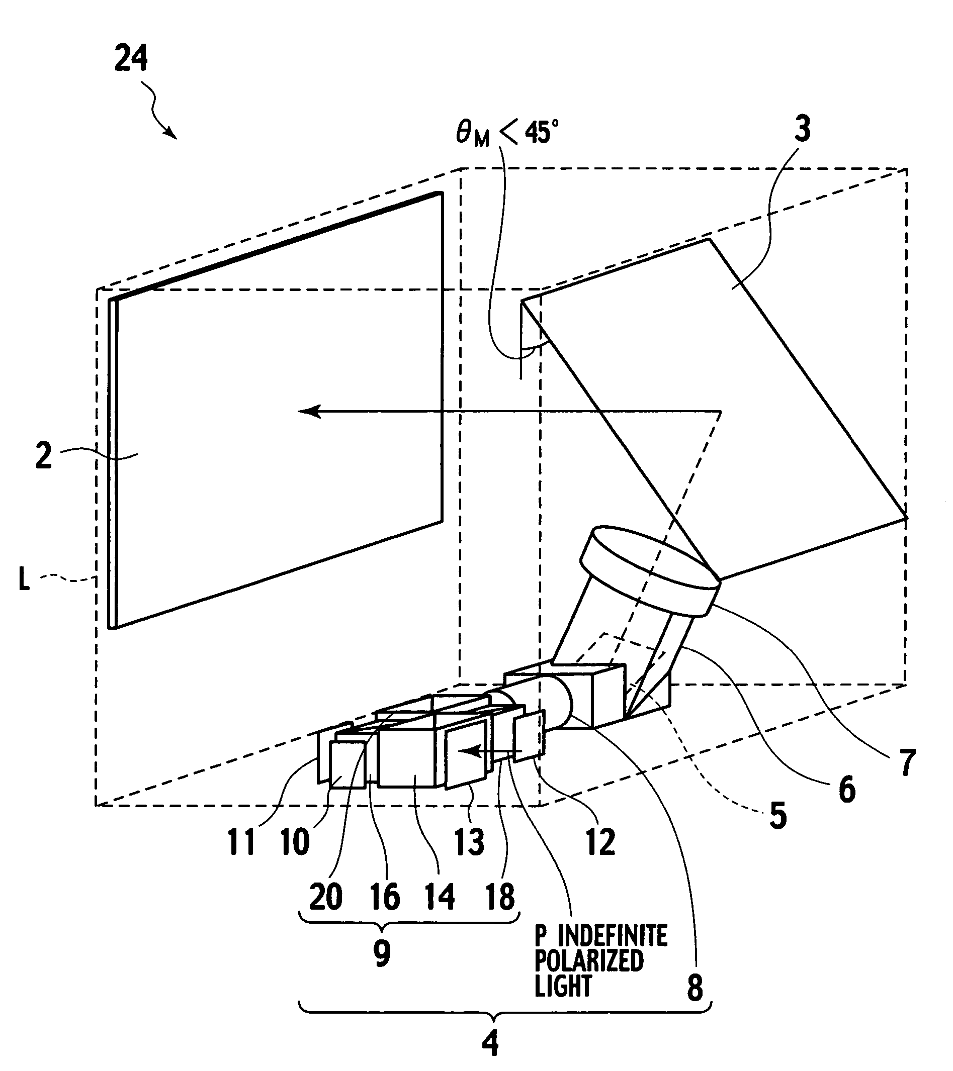
[0054]FIG. 4 is a perspective view showing a second embodiment of the image display apparatus according to the present invention. FIG. 5 is a view illustrating an arrangement of a reflecting mirror according to the second embodiment.
[0055]In FIG. 4, constituent components accommodated in a box member L are indicated by solid lines, and the box member L is indicated by broken lines for the convenience's sake.
[0056]Like reference numerals denote structures equal to those in the first embodiment, thereby eliminating their explanation.
[0057]As shown in FIG. 4, an image display apparatus 24 according to the second embodiment of the present invention has a plane mirror 3 arranged at an angle θM2 in the image display apparatus 1 in the first embodiment. Moreover, as shown in FIG. 5, an incident light axis 21 of image light which falls on a reflecting mirror 5 is within an XZ p...
third embodiment
[0061]A third embodiment according to the present invention will now be described with reference to FIG. 6.
[0062]FIG. 6 is a perspective view showing a third embodiment of the image display apparatus according to the present invention.
[0063]In FIG. 6, constituent components accommodated in a box member L are indicated by solid lines, and the box member L is indicated by broken lines for the convenience's sake.
[0064]As shown in FIG. 6, an image display apparatus 25 according to the third embodiment of the present invention has a plane mirror 26 arranged between the projection lens 7 and the plane mirror 3 in the image display apparatus 24 according to the second embodiment, and any other configuration is the same as the foregoing embodiment.
[0065]According to the third embodiment of the present invention, since the plane mirror 26 is required; the number of components is increased. However, since image light projected from the projection lens 7 is once reflected by the plane mirror 2...
PUM
 Abstract
Description
Claims
Application Information
 - R&D
- Intellectual Property
- Life Sciences
- Materials
- Tech Scout
- Unparalleled Data Quality
- Higher Quality Content
- 60% Fewer Hallucinations
Browse by: Latest US Patents, China's latest patents, Technical Efficacy Thesaurus, Application Domain, Technology Topic, Popular Technical Reports.
© 2025 PatSnap. All rights reserved.Legal|Privacy policy|Modern Slavery Act Transparency Statement|Sitemap|About US| Contact US: help@patsnap.com


