Obtaining method of image variant artistic distortion figure

A variant and image technology, applied in image enhancement, image analysis, image data processing, etc., can solve time-consuming and labor-intensive problems, and achieve low cost, fast computing speed, and remarkable visual effects

Active Publication Date: 2015-12-30
CENT SOUTH UNIV
View PDF3 Cites 3 Cited by
  • Summary
  • Abstract
  • Description
  • Claims
  • Application Information

AI Technical Summary

Problems solved by technology

[0006] The technical problem to be solved by the present invention is to provide a method for obtaining an image variant art distortion map, which overcomes the time-consuming and labor-intensive problem caused by the prior art mainly relying on manual drawing of the image variant distortion map, so as to achieve faster and more convenient Develop more image variant warp map works

Method used


Image

  • Obtaining method of image variant artistic distortion figure
  • Obtaining method of image variant artistic distortion figure
  • Obtaining method of image variant artistic distortion figure

Examples


Embodiment 1

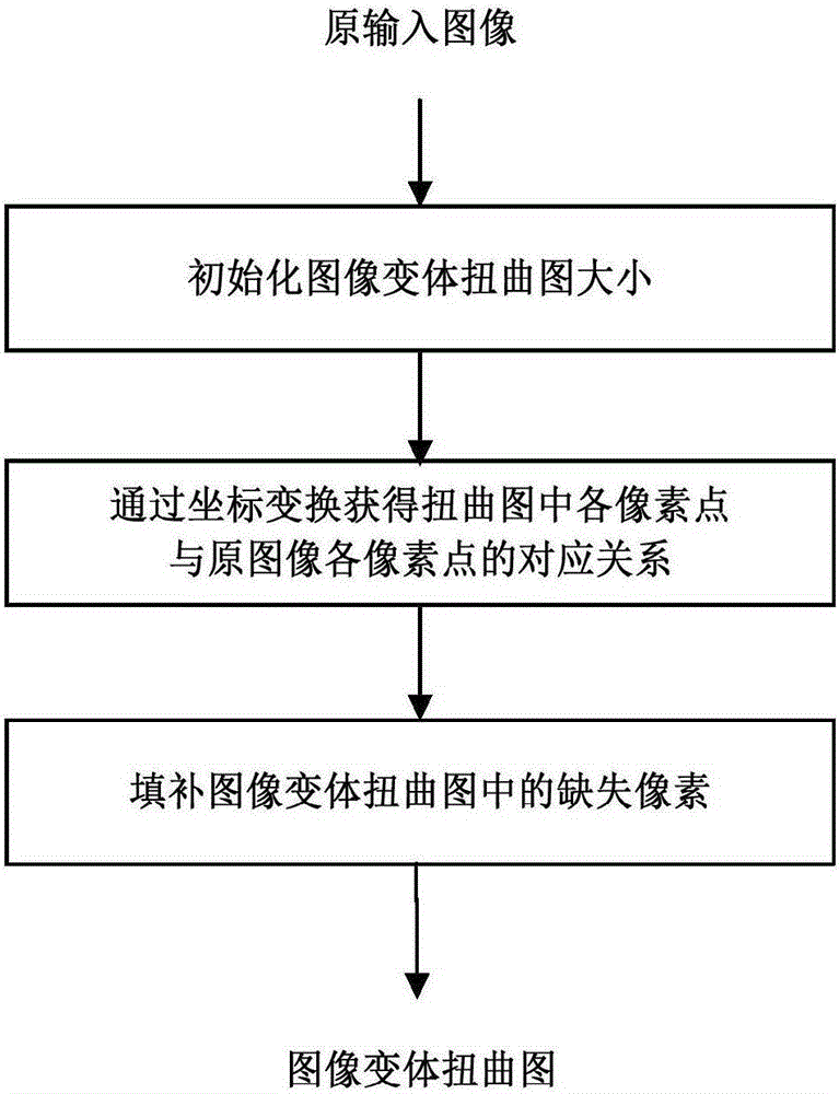
[0050] This embodiment is aimed at the acquisition of cylinder variant twisted graphs, such as figure 1 As shown in , obtaining the corresponding cylindrical variant distortion map from the original input image is carried out in the following three steps:

[0051] Step A: Initialize the size of the cylindrical variant distortion map;

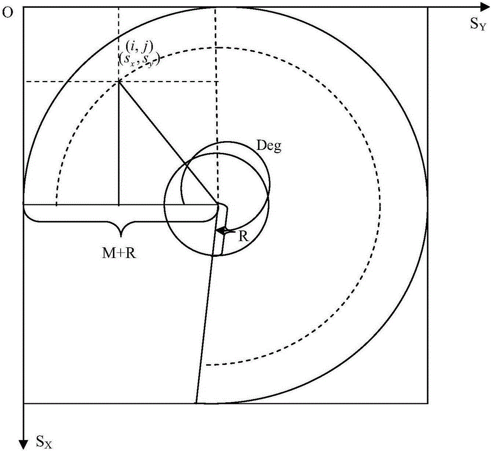
[0052] For the original input image ( Figure 6 a) Calculation of the twisted image of the cylindrical variant, the size of which is 800×500, that is, the values ​​of M and N are 500 and 800 respectively. Set the radius R of the cylindrical reflective column to 300, then the size of the cylindrical variant distortion map corresponding to this image will be initialized to (2×(R+M))×(2×(R+M))=1600×1600 .

[0053] The corresponding relationship between each pixel in the distorted image and each pixel in the original input image obtained through coordinate transformation is as follows: figure 1 The second step in the process of obtaining the twi...

Embodiment 2

[0072] This embodiment is aimed at the acquisition of the conic variant distortion map. There are three main steps to obtain the corresponding conic variant distortion map from the original input image:

[0073] Step A: Initialize the size of the conic variant distortion map;

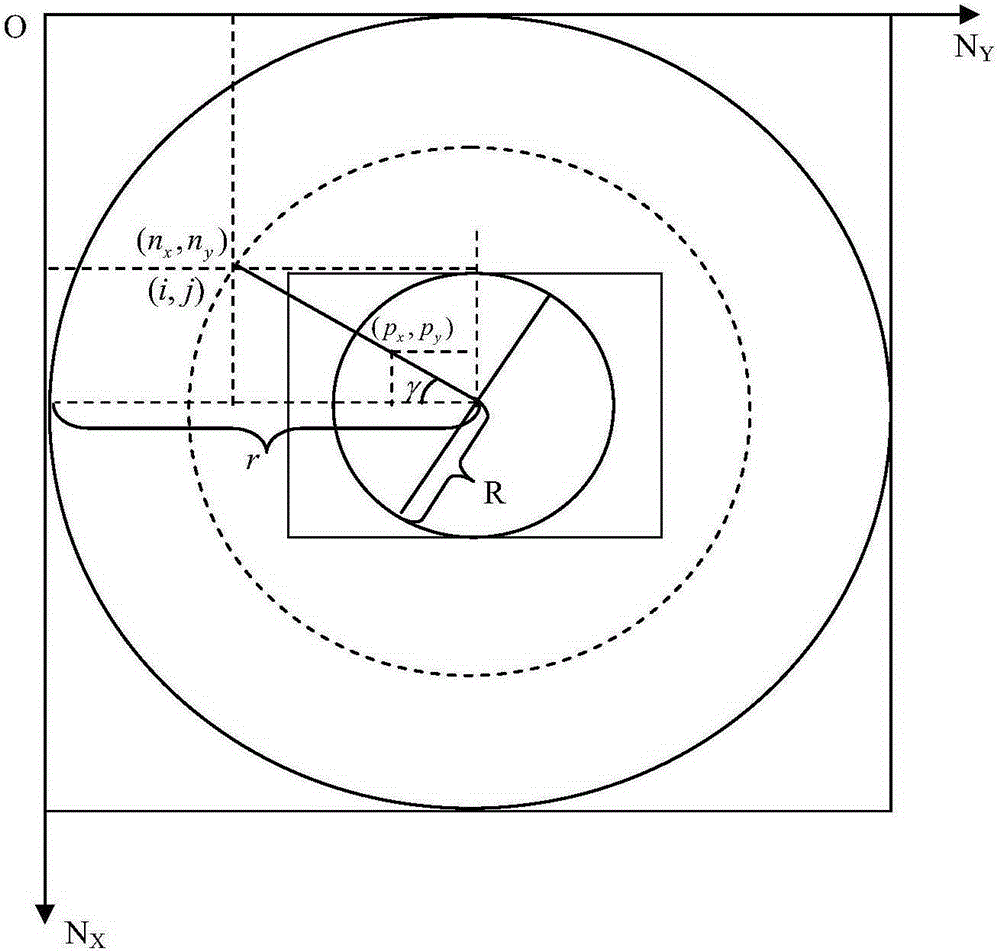
[0074] For the original input image ( Figure 7 a) Calculation of the conic variant distortion map, the size of which is 477×357, that is, the values ​​of M and N are 357 and 477 respectively. Set the radius R of the conical reflective medium to 80, and the cone angle θ to 60°, then the size of the conical variant distortion map corresponding to this image will be initialized to 2r×2r=482×482, where

[0075] r=R+R / sin((θ / 2)×(π / 180))=241;

[0076] Among them, the values ​​of the radius R and the cone angle θ of the reflective cone mainly depend on the actual size of the conical object as the reflective medium. The larger the R value, the larger the radius of the central circle of the conic variant dis...


PUM


Abstract

The invention provides an obtaining method of an image variant artistic distortion figure. The method includes the following steps that A, the size of the image variant distortion figure is initialized; B, the coordinate of any point on the image variant distortion figure is represented through a polar coordinate system with a cylinder or a conical center being a circle center, the corresponding relation of the coordinate of any point and an image coordinate system of the image variant distortion figure is determined, and meanwhile the relation between the coordinate of any point and original input image pixel point coordinates is established; C, pixel values of original input image points are assigned to relevant pixel points of the image variant distortion figure. According to the method, by means of the space coordinate conversion relation, the corresponding relation between pixel coordinate points of the distortion figure and an original image (an image displayed through a reflector) is obtained, pixel points of the original input image are assigned to corresponding distortion figure pixels, and therefore the distortion figure is obtained. By means of the method, participation of users is little, and the image variant distortion figure with a good visual effect can be obtained.

Description

technical field [0001] The invention belongs to the field of image information processing, and in particular relates to a method for obtaining an image variant art distortion map. Background technique [0002] Image morphing technology refers to a painting art that draws distorted images. When appreciating the variant image, the viewer needs to be in a specific position, and can only see the image with the normal object image with the help of a special reflective medium. The word image variant comes from the English word "Anamorphosis", which means "to change the image". Therefore, the image morphing technology mainly refers to changing the image image so that the image in the picture appears distorted in a general way. Only when viewed from a specific angle and observed with the help of a special reflective medium, can the objects in the picture return to normal. [0003] Image variation art has broad application prospects and commercial value. For example, the Danish d...

Claims


Application Information

Patent Timeline
IPC IPC(8): G06T5/50G06T3/40G06T7/00
Inventor 郭璠邹北骥刘丽珏陈建瑄卢飞张伏旭
Owner CENT SOUTH UNIV
Why Eureka
Try Eureka