
Open-type transformer three-dimensional wound core

A three-dimensional wound iron core and transformer technology, applied in transformer/inductor magnetic core, transformer/inductor parts, electrical components, etc., can solve problems such as difficult joint position processing, increased transformer loss, and inability to produce transformers , to achieve the effects of small harmonics, increased lamination coefficient, and large capacity

Active Publication Date: 2018-02-23
鑫大变压器有限公司
View PDF5 Cites 4 Cited by
  • Summary
  • Abstract
  • Description
  • Claims
  • Application Information

AI Technical Summary

Problems solved by technology

The disadvantage is that the coil must be wound on the finished core column, and a special winding machine must be used, resulting in increased investment in production equipment, and due to equipment limitations, it is also impossible to produce transformers with larger capacity
Since the core is completely enclosed, the coil cannot be removed, and once the coil fails, repairs will be very difficult
[0003] At present, open wound cores are also used in the production of three-dimensional wound core transformers, but the opening positions are all on the core column of the transformer, so once the coil is inserted, it is difficult to deal with the seam position
Moreover, the seam method leads to an increase in reluctance, which increases the loss of the transformer

Method used


Image

  • Open-type transformer three-dimensional wound core
  • Open-type transformer three-dimensional wound core
  • Open-type transformer three-dimensional wound core

Examples


Embodiment Construction

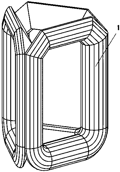
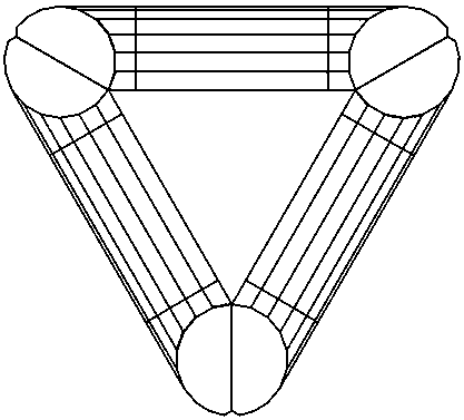
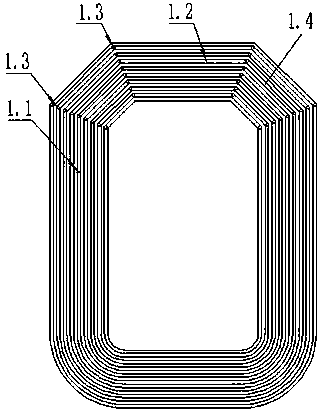
[0014] see figure 1 , which consists of three identical core frames 1 made of silicon steel sheets, see Figure 3-5 , each iron core frame 1 is composed of an upper half frame 1.2 and a lower half frame 1.1 to form a hexagonal frame. The hexagonal shape is formed by chamfering the two upper corners of the rectangular frame. It Including two iron core frame chamfering edges 1.4 in the upper left corner and upper right corner; the upper half frame has two left and right upper half frame chamfering edges 1.4.2, and the lower half frame has two left and right lower half frame chamfering edges 1.4.1, The silicon steel sheets of the two chamfered sides on the same side of the upper and lower half frames are arranged in a staggered manner. The silicon steel sheets of the two chamfered sides on the same side are inserted together to form the chamfered side 1.4 of the iron core frame. The connection of each layer of silicon steel sheets Seam 1.3 is at the bend of the silicon steel she...


PUM

PropertyMeasurementUnit
angleaaaaaaaaaa

Abstract

The invention provides an open-type transformer three-dimensional wound iron core. The gist of the invention is that it consists of three identical core frames made of silicon steel sheets, and each core frame is surrounded by an upper half frame and a lower half frame to form six Composed of border frames; the upper half frame has two left and right upper half frame chamfered edges, the lower half frame has left and right lower half frame chamfered edges, and the silicon steel sheets on the same side of the upper and lower half frames are staggered Arrangement, the silicon steel sheets of the two chamfered sides on the same side are inserted together to form the chamfered side of the iron core frame, and each layer of silicon steel sheets is connected at the bend of the silicon steel sheets. The positive effect of the invention is that the position of the joint of the iron core is completely outside the coil, and the position of the joint can be tightened very conveniently after being inserted into the coil, which is very beneficial to reducing the noise and loss of the transformer. If a fault occurs, the upper half frame of the iron core can be removed conveniently and the coil can be pulled out for maintenance.

Description

technical field [0001] The invention relates to a three-dimensional wound iron core of a transformer, which is used for a three-phase wound iron core oil-immersed transformer or a dry-type transformer. Background technique [0002] The traditional three-dimensional wound core is composed of three identical rectangular core frames wound with continuous silicon steel sheets. The disadvantage is that the coil must be wound on the finished iron core column, and a special winding machine must be used, which leads to increased investment in production equipment, and due to equipment limitations, it is also impossible to produce a transformer with a larger capacity. Because the core is completely enclosed, the coil cannot be removed, and once the coil fails, repairs will be very difficult. [0003] At present, open wound cores are also used in the production of three-dimensional wound core transformers, but the opening positions are all on the core column of the transformer, so it...

Claims


Application Information

Patent Timeline
Patent Type & Authority Patents(China)
IPC IPC(8): H01F27/26H01F27/245
Inventor 关庆罡
Owner 鑫大变压器有限公司
Learn More