Improved type head press type one-time blood collecting device

A disposable, blood-collecting device technology, applied in the field of safe blood-collecting devices, can solve the problems of increased pressure on the blood-collecting site, poor pressing feeling, inconvenience and the like

Active Publication Date: 2016-01-06
STERILANCE MEDICAL SUZHOU
View PDF6 Cites 6 Cited by
  • Summary
  • Abstract
  • Description
  • Claims
  • Application Information

AI Technical Summary

Problems solved by technology

This not only brings inconvenience to the operator, but also makes the pressure of the blood collection site significantly increased, causing psychological burden before the puncture pain

Method used


Image

  • Improved type head press type one-time blood collecting device
  • Improved type head press type one-time blood collecting device
  • Improved type head press type one-time blood collecting device

Examples


Embodiment 1

[0044] Embodiment 1: Twist cap type head push type disposable blood collection device

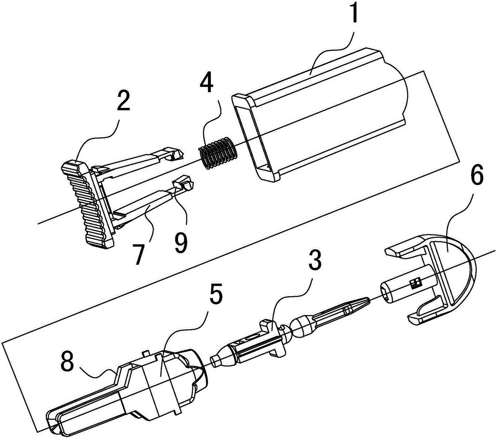
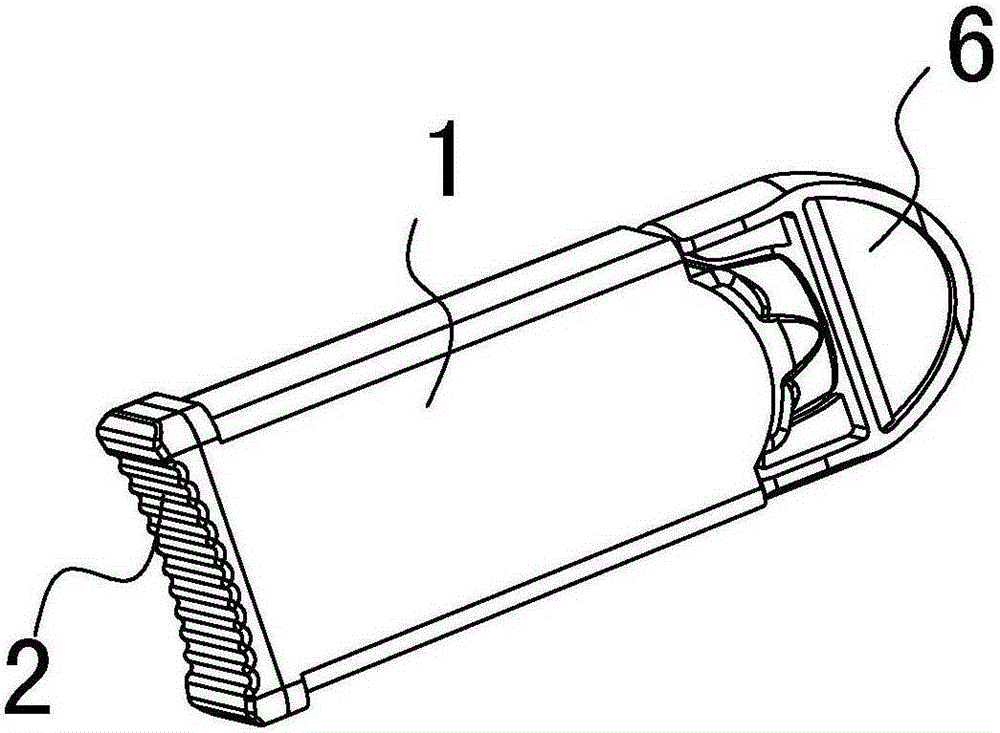
[0045] see Figure 5-Figure 10 As shown, the disposable blood collection device is composed of a housing 1, a tail cap 2, a needle core 3, a spring 4, a pusher 5 and a twist cap 6 (see Figure 5 and Figure 6 ).

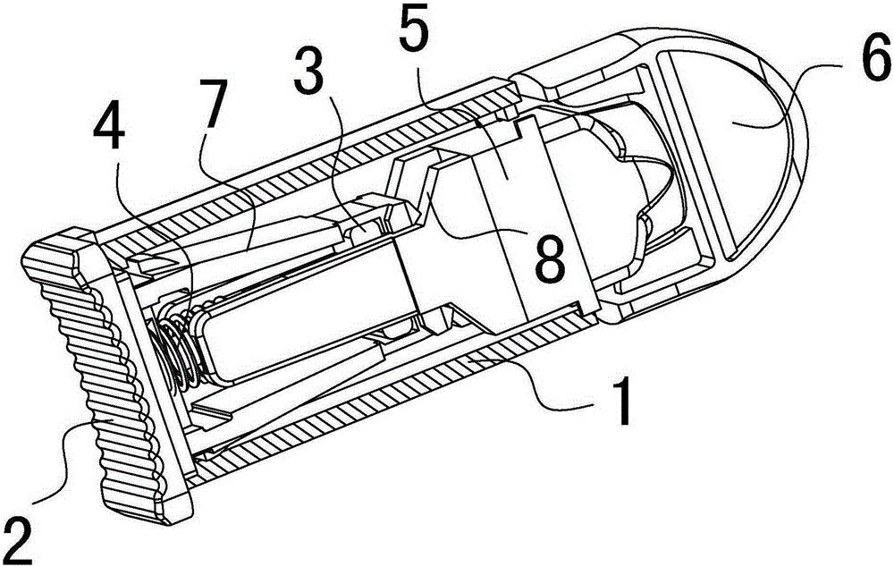
[0046] In assembled state (see Figure 9 ), the tail cover 2 covers the tail port of the housing 1, and the tail cover 2 protrudes from the housing 1 with two elastic claws 7 arranged face to face and symmetrically, and these two elastic claws 7 jointly form an elastic clip. The needle core 3 is clamped in the elastic clip, the spring 4 presses the tail of the needle core 3 and acts on the ejection direction of the needle core 3, and the elastic clip uses the hook 9 at the end and the clamping force to clamp the needle core 3 Clip to form lock before firing. The head of the pusher 5 protrudes from the front end of the shell 1, and the body of the pusher 5 is slidably connecte...

Embodiment 2

[0049] Embodiment 2: Cap type head push type disposable blood collection device

[0050] see Figure 11-Figure 13 As shown, the disposable blood collection device is made up of a shell 1, a tail cap 2, a needle core 3, a spring 4, a pusher 5 and a cap 15 (see Figure 11 and Figure 12 ). Assembly structure see Figure 13 shown.

[0051] The difference between this embodiment and Embodiment 1 lies in that the structure of the protective cap is different. What embodiment 1 draws blood is twist cap type structure, and what this embodiment adopts is cap type structure. The cap type structure means that the head of the blood collection device adopts a cap structure, that is, the cap 15 is set on the head of the blood collection device, and a detection rod protrudes from the cap 15, which can be used to detect the locking state of the needle core and protect the needle tip. Both the twist cap structure and the block cap structure are prior art.


PUM


Abstract

An improved type head press type one-time blood collecting device comprises a casing, a pin core, a spring and a push ejection device, and an elastic clamp used for clamping and locking the pin core is arranged in the casing; the device is characterized in that a yielding space is formed in the tail end of the elastic clamp in a lateral opening direction; a stop block and an inclined surface are arranged on the push ejection device; in a locking state before ejection, the stop block occupies the yielding space so as to limit the lateral opening amplitude of the elastic clamp; during press ejection, the pushing device moves back and forth in the casing and drives the stop block to leave the yielding space, at the same time, the inclined surface of the push ejection device forces an elastic claw to open laterally, and the pin core is guided to produce ejection puncture. According to the improved type head press type one-time blood collecting device, the allowed opening amplitude of the elastic clamp is controlled by controlling the side yielding space, and finally, the reliability whether the pin core breaks away from clamping of the elastic clamp can be effectively controlled. The mechanism reliability problem caused by clamping force of the elastic clamp in a blood collecting device ejection mechanism and the problem between the use and the hand feeling are solved.

Description

technical field [0001] The invention relates to the field of medical blood collection instruments, in particular to a head-pressing disposable safety blood collection device (or blood collection needle) with an ejection mechanism. Background technique [0002] In the field of medical blood collection, disposable blood collection devices are popular among medical staff and patients for their small size, safe use, and convenient operation. They are currently widely used in various medical institutions and diabetic patients. This kind of blood collection device has its own ejection mechanism, compact structure, one-time use as a whole, safe and convenient, so it has strong market development potential. [0003] Chinese patent CN2619583Y once announced the authorization of a utility model patent titled "Self-Locking Disposable Safety Automatic Blood Collection Needle". This patent provides a representative traditional cap-type head-pressing disposable blood collection device. ...

Claims


Application Information

Patent Timeline
Patent Type & Authority Applications(China)
IPC IPC(8): A61B5/15
Inventor 施国平曹跃平
Owner STERILANCE MEDICAL SUZHOU
Why Eureka
Try Eureka