Eureka AIR delivers breakthrough ideas for toughest innovation challenges, trusted by R&D personnel around the world.

Caster with braking device

A technology for brakes and casters, which is applied to casters, wheels, motor vehicles, etc., can solve the problems of heavy weight, complicated brake release operations, and increased costs, and achieve the effect of improving versatility

Active Publication Date: 2016-01-06
HINOMOTO JOMAE
View PDF5 Cites 6 Cited by
  • Summary
  • Abstract
  • Description
  • Claims
  • Application Information

AI Technical Summary

Problems solved by technology

[0004] However, in conventional casters with brakes having such brake operating pedals, since the brake operating pedals are respectively provided on each of the plurality of casters, there is a problem that if the brake operating pedals are not provided for each If the pedal is used to operate the brake, the entire trolley cannot be stopped (braked), and the operation of the brake (brake) and its release are complicated, and braking takes time.
[0007] However, in the above-mentioned latter conventional caster, as a transmission mechanism, since there is a link mechanism using a metal shaft, a rod, a connecting rod, etc., in addition to the complicated structure of the transmission mechanism itself, there are also Problems such as: overall large-scale weighting and cost increase
[0008] In addition, since the brake operating pedal and the U-shaped operating lever are arranged near the casters such as the bottom plate of the trolley, they are not arranged in front of or near the hand of the user who uses the trolley, so there is also the problem that the brake operating pedal and the The operation of the U-shaped joystick is complicated
[0009] In addition, since the brake operating pedal and the U-shaped operating lever are foot-depressed structures, they are often arranged on the bottom of a trolley or cart that is easy for the user to operate with their feet. There is a problem that it is difficult to fit the trolley Various shapes of mounted objects such as carts

Method used


Image

  • Caster with braking device
  • Caster with braking device
  • Caster with braking device

Examples


Embodiment Construction

[0027] Embodiments of the present invention will be described below with reference to the accompanying drawings. In addition, the same code|symbol is attached|subjected to the same or equivalent part in several drawings.

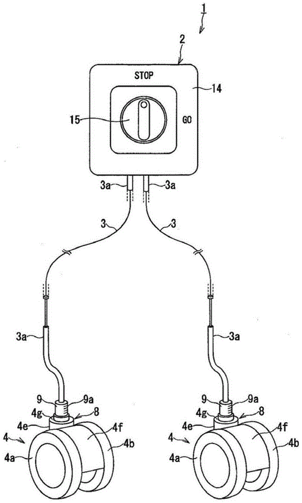
[0028] figure 1 It is a perspective view which shows the whole structure of the caster with brake 1 which concerns on this embodiment, and partially abbreviates. as it should figure 1 As shown, on the operation unit 2 of the caster 1 with brakes, there are multiple flexible metals, such as two transmission wires 3, 3, and multiple, such as two first casters made of synthetic resin. 4, 4.

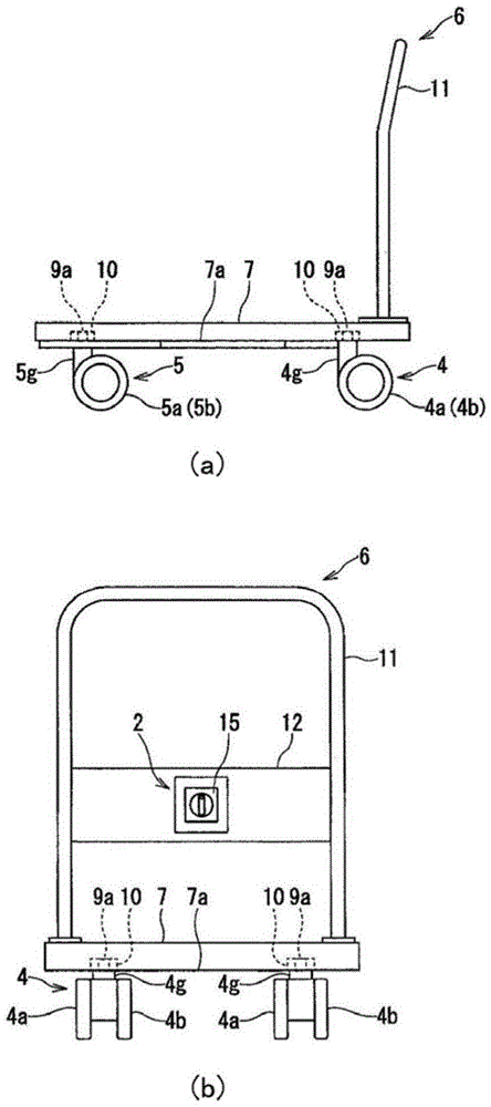
[0029] like figure 2 As shown in (a) and (b), these two first casters 4, 4 are respectively arranged on metal, etc. On the outer bottom surface of each corner of the bottom 7 of the trolley 6.

[0030] That is, the bottom 7 of the trolley 6 is formed into a shape such as a flat bottom corner by sheet metal, etc., and a pair of left and right second casters 5, 5 are ...


PUM


Abstract

The invention provides a caster with a braking device. The caster comprises the following components: a caster body, an annular engaging step formed at a side of a wheel, and a plurality of axle-pin rakes with a hollow vibrated shaft which are rotatably arranged on the caster body; an operating unit, which is provided with a rotary knob for braking rotation of a plurality of axle-pin rakes and releasing the braking operation by manual operation, and an operation part for making a plurality of transmission wires reciprocate at an axial direction according to braking operation and braking releasing operation of the rotary knob; a plurality of transmission wires; a braking unit, which brakes the wheel by engaging the annular engaging step to the axle-pin rakes according to reciprocation of the axial direction of the transmission wires, and releases the braking of the wheel by releasing engagement of the annular engaging step to the axle-pin rakes.The caster can be used for braking operation and releasing operation by using a manual operation easily, the caster can be installed on trolleys of various shapes and other objects to be installed with university.

Description

technical field [0001] The present invention relates to a caster with a brake installed on a mounted object such as a trolley or a cart, and more particularly to a caster with a brake provided with a device for stopping (braking) the rotation of the wheel of the caster main body. brakes. Background technique [0002] In the past, as an example of such a caster with a brake, a plurality of casters are provided on a mounted body such as a trolley or a cart, and each of these casters is respectively equipped with a wheel that attaches the caster. A pedal for operating a brake and a U-shaped operating lever for locking the rotation and stopping the rotation (refer to Patent Document 1). [0003] The user locks the wheel of the caster wheel by stepping on these brake operating pedals and the U-shaped operating lever, and on the other hand, lifts the foot upward to release the brake. [0004] However, in conventional casters with brakes having such brake operating pedals, since ...

Claims


Application Information

Patent Timeline
IPC IPC(8): B60B33/00B62B5/04
Inventor 今野谦太郎
Owner HINOMOTO JOMAE
Why Eureka
Eureka Blog
Learn More