Conveying mechanism for cement materials

A conveying mechanism and cement technology, applied in the direction of conveyors, transportation and packaging, etc., can solve the problems of troublesome adjustment, inability to clearly control the amount of conveying, low efficiency, etc., and achieve the effect of accurate adjustment

Active Publication Date: 2016-01-06
中材萍乡水泥有限公司
View PDF7 Cites 9 Cited by
  • Summary
  • Abstract
  • Description
  • Claims
  • Application Information

AI Technical Summary

Problems solved by technology

[0002] When cement slabs or cement substrates are used, the cement needs to be transported. The existing method generally uses a belt to transport, and the transport method is to directly place the cement on the belt for transport. The amount of transport cannot be clearly controlled, and The tension adjustment of the existing conveyor belts is realized by manually adjusting the screw, which is troublesome to adjust and low in efficiency.

Method used


Image

  • Conveying mechanism for cement materials
  • Conveying mechanism for cement materials
  • Conveying mechanism for cement materials

Examples


Embodiment

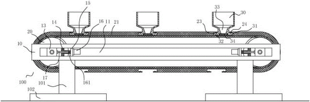
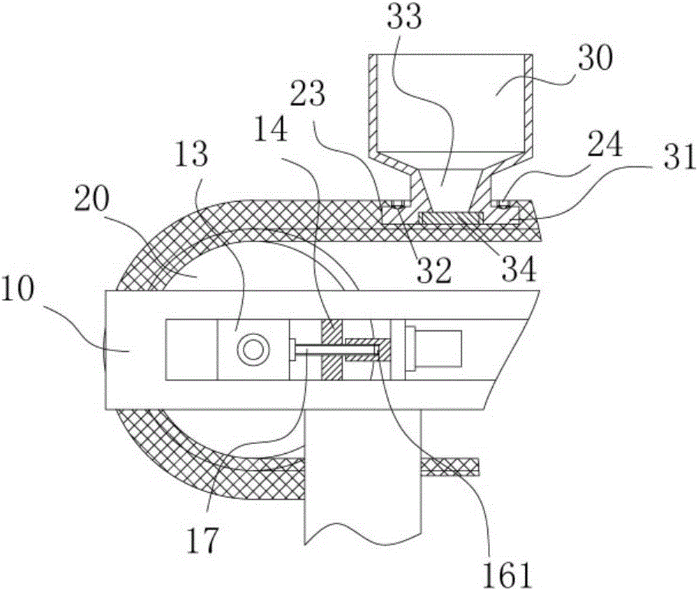
[0021] Example: see Figures 1 to 6 As shown, a cement material conveying mechanism includes a conveying frame body 100, and the conveying frame body 100 includes two adjusting beams 10, the bottoms of the two adjusting beams 10 are fixed with legs 101, and the bottoms of the legs 101 are fixed on the bottom On the connecting plate 102, the middle part of the adjusting crossbeam 10 has an elongated sliding channel 11 extending in the longitudinal direction, and the upper and lower inner side walls of the elongated sliding channel 11 have sliding grooves 12, and two sliding blocks 13 are inserted into the long The two ends of the elongated sliding groove 11, the upper top surface and the lower bottom surface of the sliding block 13 have a raised block 131, and the raised block 131 is inserted into the corresponding sliding groove 12, and the elongated sliding groove 11 is near the two ends. A middle adjusting plate 14 and an adjusting motor connecting plate 15 are fixed in the ...


PUM


Abstract

The invention discloses a conveying mechanism for cement materials. The conveying mechanism comprises a conveying frame body, wherein the conveying frame body comprises two adjustment cross beams; support legs are fixed at the bottoms of the two adjustment cross beams; the bottoms of the support legs are fixed on bottom connection parts respectively; a long slide through groove which extends along a length direction is formed in the middle part of each adjustment cross beam; slide grooves are formed in the upper inner sidewall and the lower inner sidewall of each long slide through groove; two slide blocks are bushed in the two ends of each long slide through groove; bulged blocks are arranged on the upper top surface and the lower bottom surface of each slide block; each bulged block is bushed in the corresponding slide groove; a middle adjustment plate and an adjustment motor connection plate are fixed in each long slide through groove and close to the two ends; a fine adjustment motor is fixed on each adjustment motor connection plate; one end of each adjustment screw is hinged on the corresponding slide block, the other end of each adjustment screw is screwed in a screwing hole formed in the output shaft of the corresponding fine adjustment motor, and the middle part of the adjustment screw is screwed to the corresponding middle adjustment plate. The conveying mechanism is capable of adjusting the tensioning degree of a conveying belt through the fine adjustment motors, the adjustment is accurate, and manual adjustment is not needed.

Description

Technical field: [0001] The invention relates to the technical field of building material machinery and equipment, and more specifically relates to a cement material conveying mechanism. Background technique: [0002] When cement slabs or cement substrates are used, the cement needs to be transported. The existing method generally uses a belt to transport, and the transport method is to directly place the cement on the belt for transport. The amount of transport cannot be clearly controlled, and The tension adjustment of the existing conveyor belts is realized by manually adjusting the screw rod, which is cumbersome to adjust and has low efficiency. Invention content: [0003] The purpose of the present invention is to provide a cement conveying mechanism aimed at the deficiencies of the prior art, which can adjust the tension of the conveying belt through a fine-tuning motor. It is very convenient to fix the feeding bucket directly on the conveyor belt. [0004] Technic...

Claims


Application Information

Patent Timeline
IPC IPC(8): B65G23/44B65G15/58
Inventor 董芬芳
Owner 中材萍乡水泥有限公司
Why Eureka
Try Eureka