Conveyor device with negative pressure suction

A conveying equipment and negative pressure technology, which is applied in the field of conveying equipment using negative pressure suction, can solve problems such as air pollution, achieve precise adjustment, and avoid the effect of mass distribution

Active Publication Date: 2010-11-17
KOERBER TECH GMBH
View PDF6 Cites 15 Cited by
  • Summary
  • Abstract
  • Description
  • Claims
  • Application Information

AI Technical Summary

Problems solved by technology

This is all the more problematic when the delivery device is used to deliver tobacco or filter rods, because these items are not only strongly breathable (and therefore always require a particu

Method used


Image

  • Conveyor device with negative pressure suction
  • Conveyor device with negative pressure suction
  • Conveyor device with negative pressure suction

Examples


Embodiment Construction

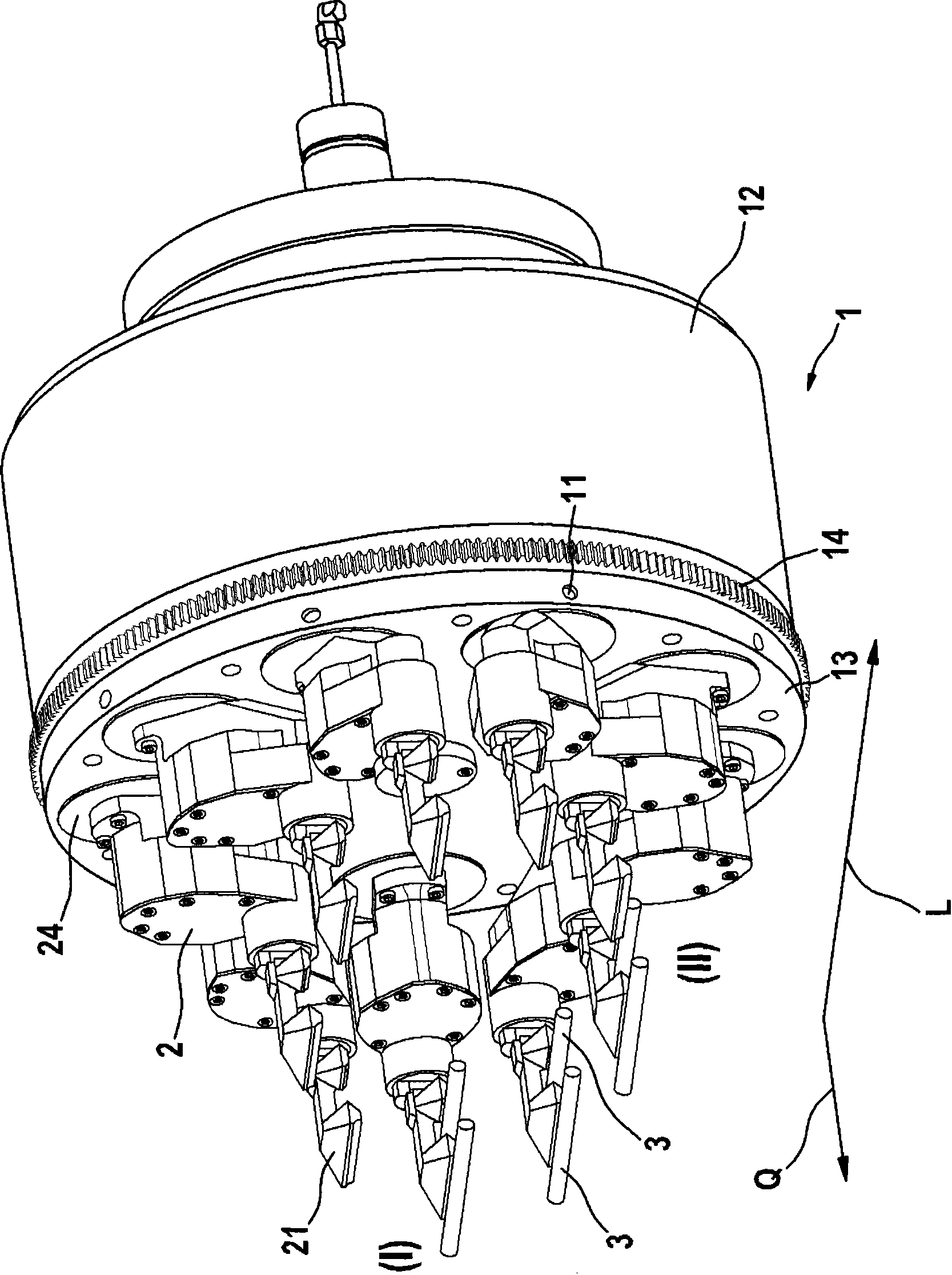
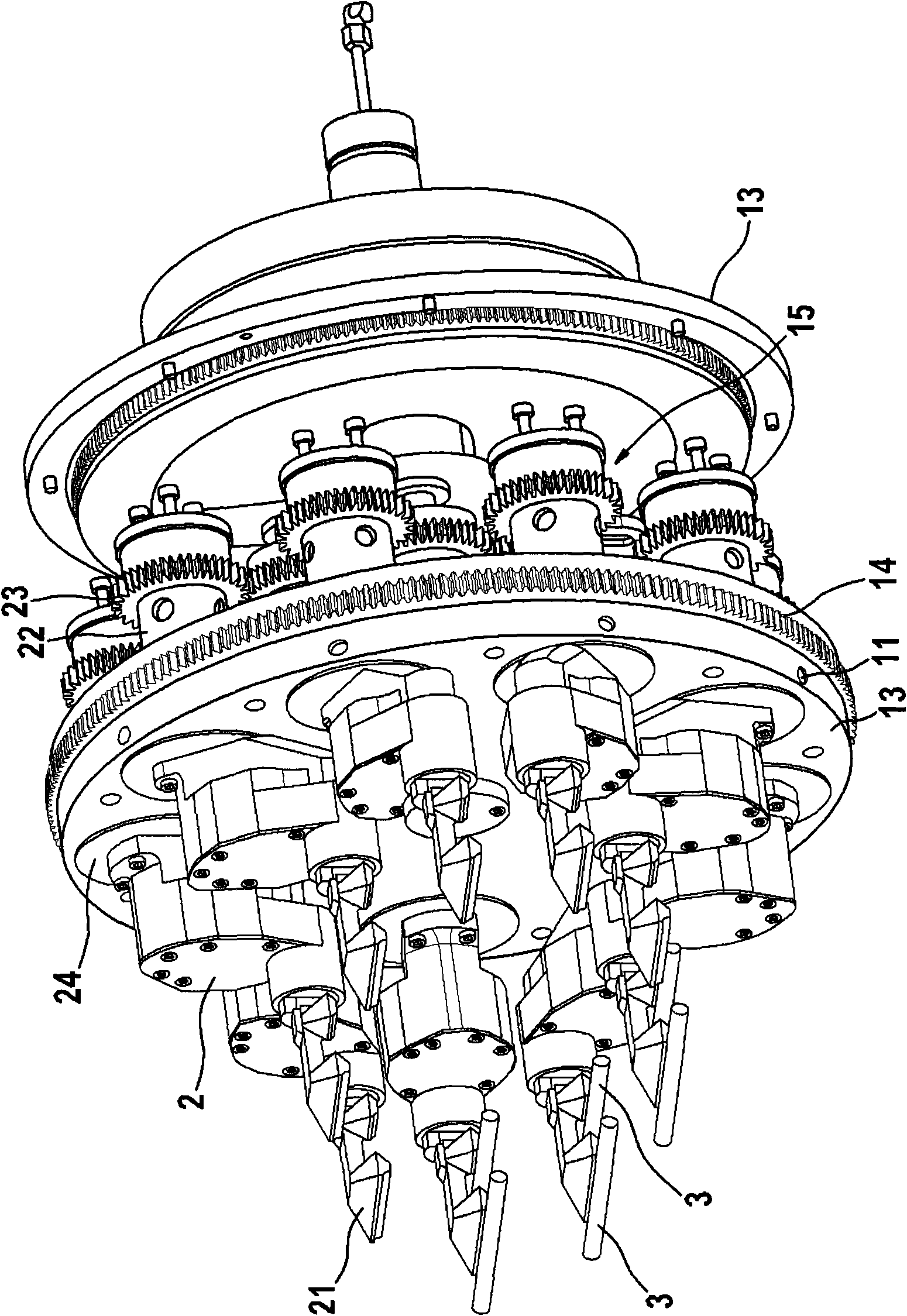
[0086] In Figure 2 to Figure 5 A device according to a first embodiment of the invention is described in . Figure 6 to Figure 1 1 shows a device according to a second embodiment of the invention. For more clarity, in image 3 ,Figure 4, Image 6 , Figure 7 And the retaining head is not shown in Fig. 11. For the same reason, in Figure 7 , Figure 10 , Figure 11A with Figure 11B The hatching of the section is omitted in , and in Figure 7 The revolutions are not shown in and 11, which are located behind the cutting plane and are partially covered by the cutting revolutions. Unless otherwise stated, the same reference numerals denote the same elements or regions herein.

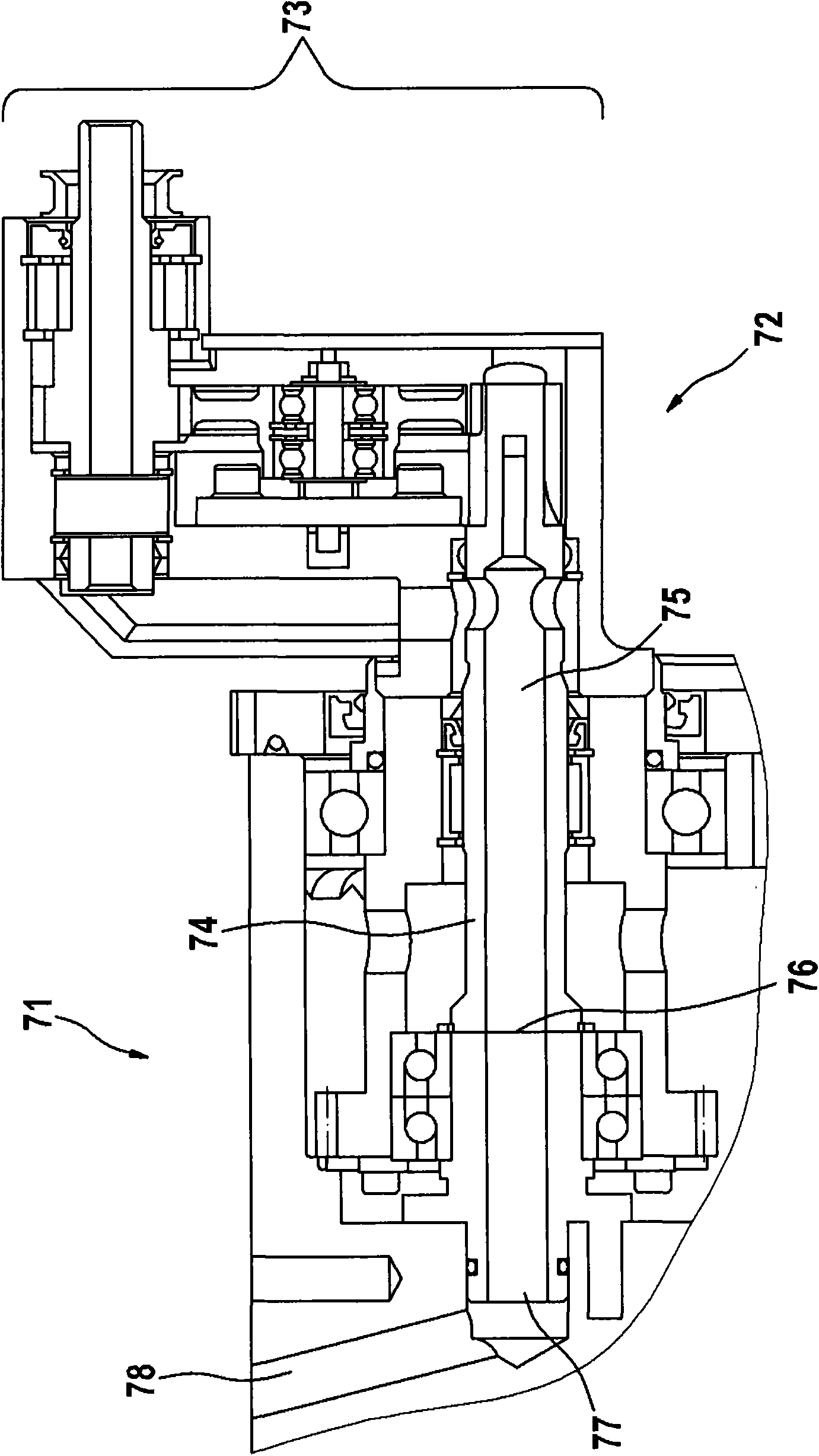
[0087] exist Figure 2A In , a longitudinal conveyor according to a first embodiment of the invention is shown. The base body 1 is designed as a drum roller mounted rotatably about its central axis, which is driven via a central shaft during normal operation (that is to say for conveying rod-sh...


PUM


Abstract

The invention relates to a conveyor device with negative pressure suction, specifically to a conveyor for diversion of bar shape article from transmission stream in vertical axis direction to the transmission stream in the cross axis direction or the inverse, which includes a longitudinal conveyor. The longitudinal conveyor has a substrate that can be rotatably supported and a plurality of revolving bodies at sides of the substrate and can rotatably support the substrate. Each revolving body has at least one holding head for holding the bar shape article by the negative-pressure. The negative-pressure is fed to the revolving body through a control panel, the control panel is used to open and cut off the negative-pressure pipeline to modulate part of the surface valve of the negative-pressure at the holding head. The opening and closing of the surface valve winds the neck axes by the revolving body and is caused by the rotary movement relative to the basal body. The control characteristic of the surface valve is determined by the physical dimension and position on the circular shape notch on the control panel. Furthermore, presented is a method for diversion of bar shape article based on rotary movement of the revolving body relative to the substrate.

Description

technical field [0001] The invention relates to a rod-shaped article conveying equipment , which serves to divert rod-shaped articles from a first transport stream (Transportstrom) into a second transport stream, wherein one of the two transport streams has a longitudinal axis relative to the rod-shaped articles Conveying direction , and the other of the two conveying streams has a conveying direction extending transversely to the conveying direction of the longitudinal axis, which is transverse to the rod-shaped article. [0002] In particular, the invention relates to a and multiple rotators vertical conveyor The delivery device, wherein the base body includes a plurality of flow holes and is mounted rotatably about its central axis (Mittelachse) for rotational movement, wherein each of the revolution bodies comprises a neck section (Schaftabschnitt), a suction channel (Ansaugkanal) and at least one holding head (Haltekopf) and is held Adjustment is used for a...

Claims


Application Information

Patent Timeline
IPC IPC(8): B65G47/22A24C5/35A24C5/00
CPCA24C5/326B65G47/848
Inventor S·施利西奥G·韦斯纳
Owner KOERBER TECH GMBH
Why Eureka
Try Eureka