An automatic edge-to-edge high-speed cloth inspection machine
A cloth inspection machine and automatic technology, which is applied in the inspection of textile materials, textiles and papermaking, etc., can solve the problems of poor use effect of winding and unwinding and cloth inspection machines, low quality of winding and unwinding, poor continuous operation ability, etc. , to achieve continuous and stable cloth inspection work, convenient disassembly, assembly, maintenance and replacement, and labor-saving effects
- Summary
- Abstract
- Description
- Claims
- Application Information
AI Technical Summary
Problems solved by technology
Method used
Image
Examples
Embodiment 1
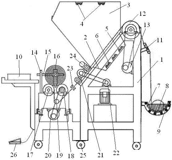
[0013] Embodiment 1: as figure 1 As shown, an automatic edge-aligning high-speed cloth inspection machine includes a frame 1 and an unwinding device arranged on the frame 1, a cloth inspection device, a winding device, an electric eye automatic edge-aligning device 23, and an electronic tension-free adjustment device , an automatic metering device 24 and an automatic control box 10, the cloth inspection device includes an inclined cloth inspection table top 2 and a condenser cover 3, the condenser cover 3 completely wraps the cloth inspection table 2, and is set on the condenser cover 3 There are multiple cloth inspection lights 4, and the cloth inspection table 2 is made of trapezoidal grooves plus non-reflective glass, and multiple sets of linear array CCD cameras 5, linear array LED light sources 6 and lenses are arranged at the bottom of the trapezoidal grooves. The bottom of frame 1 is provided with the universal wheel 25 that is convenient to move, and the front lower pa...
Embodiment 2
[0014] Embodiment 2: as figure 1 As shown, as an improvement of the present invention, the unwinding device includes a bowl-shaped cloth placing groove 7, an active cloth releasing roller 8, a zigzag frame 11 and a spreader roller 12, and the spreader roller 12 can ensure that the cloth is placed in the inspection To prevent the cloth from curling during the cloth device, the bowl-shaped cloth placing groove 7 is fixedly installed on the back of the frame 1, and a plurality of active cloth releasing rollers 8 are arranged in the bowl-shaped cloth placing groove 7, and the zigzag frame 11 is installed on the The bowl-shaped cloth is placed above the groove 7 and close to the spreader roller 12. The spreader roller 12 is driven by a cloth-running motor 13, and a belt drive is used between the spreader roller 12 and the cloth-running motor 13 shafts. An infrared detector 9 is arranged at the notch of the cloth placement groove 7, and the infrared detector 9 is electrically connec...
Embodiment 3
[0015] Embodiment 3: as figure 1As shown, as an improvement of the present invention, the winding device is arranged at the front end of the frame 1 below the cloth inspection device. , the second cloth roll 18 and the cloth roll motor 20, the cloth roll support 14 is fixedly provided with mutually perpendicular warp knitting 16 and weft knitting 15, the first roll 17 and the second roll 18 is located directly below the roll-up warp knitting 16 and the roll-up weft knitting 15, and the initial position of the roll-up warp knitting 16 is between the first cloth roll 17 and the second cloth roll 18, the cloth roll float 19 is arranged below the first cloth rolling roller 17 and the second cloth rolling roller 18, the position of the cloth rolling floating roller 19 is adjustable, and the second cloth rolling roller 17 is connected to the cloth rolling motor 20 through a belt. The rest of the structures and advantages are exactly the same as in Embodiment 1.
PUM
 Abstract
Description
Claims
Application Information
 - R&D
- Intellectual Property
- Life Sciences
- Materials
- Tech Scout
- Unparalleled Data Quality
- Higher Quality Content
- 60% Fewer Hallucinations
Browse by: Latest US Patents, China's latest patents, Technical Efficacy Thesaurus, Application Domain, Technology Topic, Popular Technical Reports.
© 2025 PatSnap. All rights reserved.Legal|Privacy policy|Modern Slavery Act Transparency Statement|Sitemap|About US| Contact US: help@patsnap.com

