Pavement sweeping apparatus

A cleaning device and housing technology, which is applied in road cleaning, cleaning methods, construction, etc., can solve the problems of rolling brushes that cannot be raised and lowered, power transmission, inflexible cleaning, and inseparable, etc., and achieve compact structure, small volume, and improved service life. Effect

Active Publication Date: 2016-01-06
QUANZHOU MINSHENG HIGHWAY TECH
View PDF6 Cites 4 Cited by
  • Summary
  • Abstract
  • Description
  • Claims
  • Application Information

AI Technical Summary

Problems solved by technology

[0004] The invention provides a road cleaning device, the main purpose of which is to overcome the problems of inflexibility and limited use of the existing trailer-type road sweeper due to its too long structure, and at the same time overcome the inability of the roller brush to lift and its power transmission. separation problem

Method used


Image

  • Pavement sweeping apparatus
  • Pavement sweeping apparatus
  • Pavement sweeping apparatus

Examples


Embodiment Construction

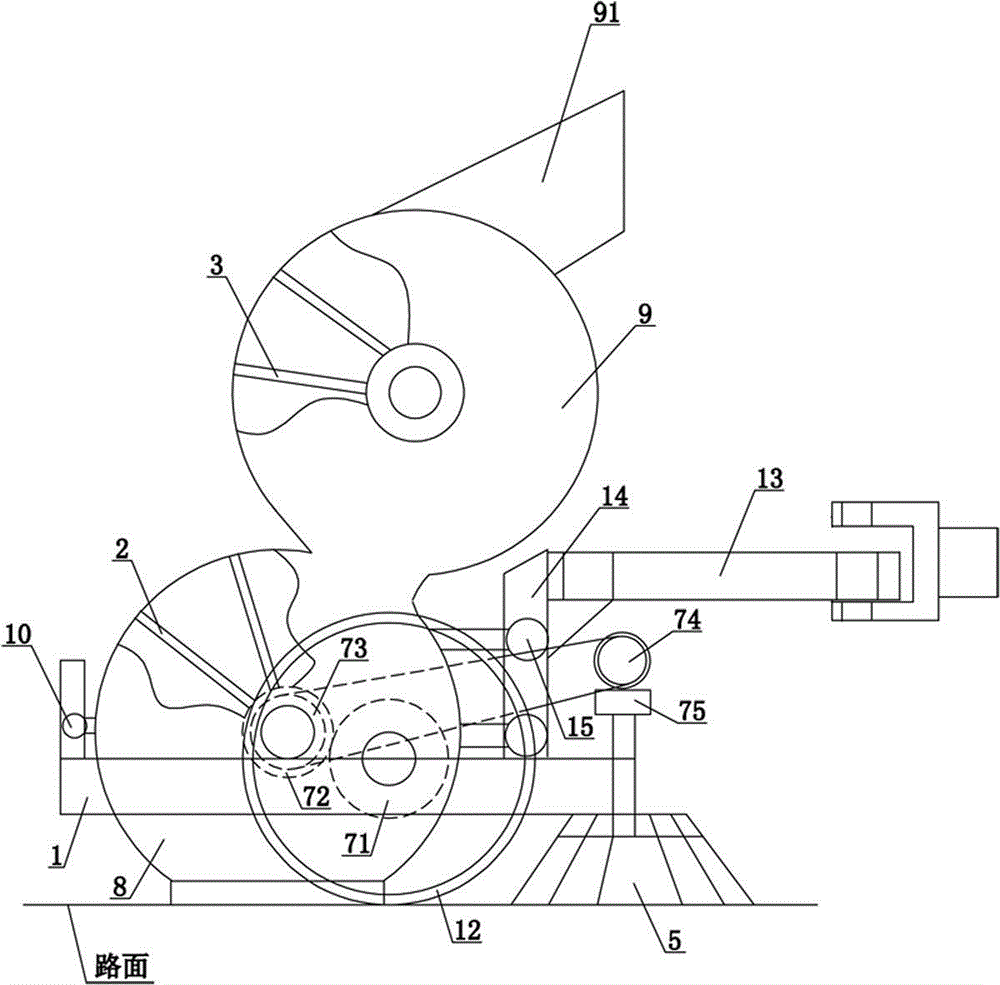
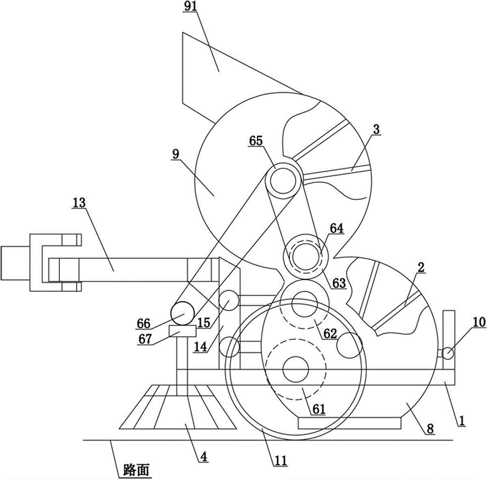
[0018] refer to figure 1 with figure 2 . A road cleaning device comprises a frame 1, a lower rolling brush 2, an upper rolling brush 3, a left brush 4, a right brush 5, a left transmission mechanism and a right transmission mechanism. The left side of the frame 1 is provided with a left wheel 11, and the right side is provided with a right wheel 12, and the left wheel 11 and the right wheel 12 are not coaxial. The lower rolling brush 2 is located in the lower casing 8, and the lower casing 8 is placed on the frame 1, and the upper rolling brush 3 is located in an upper casing 9, and the upper casing 9 is connected to the lower casing 8 above, and the upper casing 9 communicates with the lower casing 8 , and the top of the upper casing 9 is provided with a garbage outlet 91 . The left brush 4 and the right brush 5 are arranged on the front side of the lower casing 8 and connected with the lower casing 8 . The left transmission mechanism and the right transmission mechanism...


PUM


Abstract

The invention discloses a pavement sweeping apparatus. The pavement sweeping apparatus comprises a rack, a lower rolling brush, an upper rolling brush, a left side brush, a right side brush, a left transmission mechanism and a right transmission mechanism. A left wheel is arranged on the left side of the rack; a right wheel is arranged on the right side of the rack; the left wheel and the right wheel are not coaxial; the lower rolling brush is disposed inside a lower shell; the lower shell is arranged on the rack; the upper rolling brush is disposed inside an upper shell; the upper shell is connected on the lower shell; the upper shell is communicated with the lower shell; a garbage outlet is arranged at the top portion of the upper shell; the left side brush and the right side brush are arranged on the front side of the lower shell and are connected to the lower shell; the left transmission mechanism and the right transmission mechanism are respectively arranged on the left side and right side of the lower shell; the left wheel is in transmission connection with the upper rolling brush and the left side brush through the left transmission mechanism; the right wheel is in transmission connection with the lower rolling brush and the right side brush through the right transmission mechanism; an elevating mechanism is arranged on the rack and is connected to the lower shell; and a traction connecting rod is arranged at the front portion of the rack.

Description

technical field [0001] The invention relates to the field of road cleaning equipment, in particular to a road cleaning device. Background technique [0002] With the improvement of living standards and the development of society, the pollution of roads is becoming more and more serious. In order to keep the roads clean, relevant departments have invested considerable manpower and material resources in cleaning and cleaning the roads. In order to improve the cleaning efficiency of roads, mechanical cleaning has gradually replaced manual cleaning. The existing road mechanical cleaning products mainly include road sweepers with automobile structure and road sweepers with mechanical structure. Due to the high cost of using road sweepers, many users cannot bear it, making various use costs low in recent years. The mechanical road sweeper has been developed rapidly, and the most representative one should be the trailer type road sweeper. Since it does not have its own power, the ...

Claims


Application Information

Patent Timeline
Patent Type & Authority Applications(China)
IPC IPC(8): E01H1/05
Inventor 赖杰民
Owner QUANZHOU MINSHENG HIGHWAY TECH
Why Eureka
Try Eureka