Novel foam metal sand-prevention pipe

A technology of metal foam and sand control pipe, which is applied in the direction of production fluid, wellbore/well parts, earthwork drilling and production, etc. It can solve the problems of low permeability, poor flow conductivity, increase oil production, etc., and meet the requirements of sand control, Improve the sand control ability and the effect of strong diversion ability

Inactive Publication Date: 2016-01-06
CHINA UNIV OF PETROLEUM (BEIJING)
View PDF6 Cites 5 Cited by
  • Summary
  • Abstract
  • Description
  • Claims
  • Application Information

AI Technical Summary

Problems solved by technology

[0002] During the oil production process, due to geological factors and production reasons, the sand in the oil layer will flow into the well together with the oil and gas, and the bottom of the well will be blocked. In view of this situation, the mechanical sand control method is widely used in oil fields, that is, sand control pipes are placed in the oil layer. At present Commonly used sand control pipes include slotted liners, wire-wound screens, multi-layer metal mesh wound composite screens, etc. After investigation, these sand control pipes have the following disadvantages: low permeability, resulting in poor flow conductivity, and cannot effectively improve the flow rate of liquid. The flow rate is increased, the oil production rate is increased, and the filtration accuracy is not high enough, and the service life is not long, etc.
However, during the sand control experiment, it was found that most of the sand particles were deposited on the surface, resulting in a decrease in the liquid output. However, in the oilfield sand control specification, there may be a certain amount of sand output to ensure the appropriate liquid production. The analysis shows that it is because Due to the high strength and special internal structure of the metal foam, even sand particles smaller than the sand-retaining accuracy of the metal foam sand control layer cannot pass through, resulting in a sharp drop in permeability

Method used


Image

  • Novel foam metal sand-prevention pipe
  • Novel foam metal sand-prevention pipe
  • Novel foam metal sand-prevention pipe

Examples


Embodiment Construction

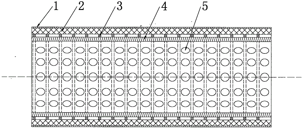
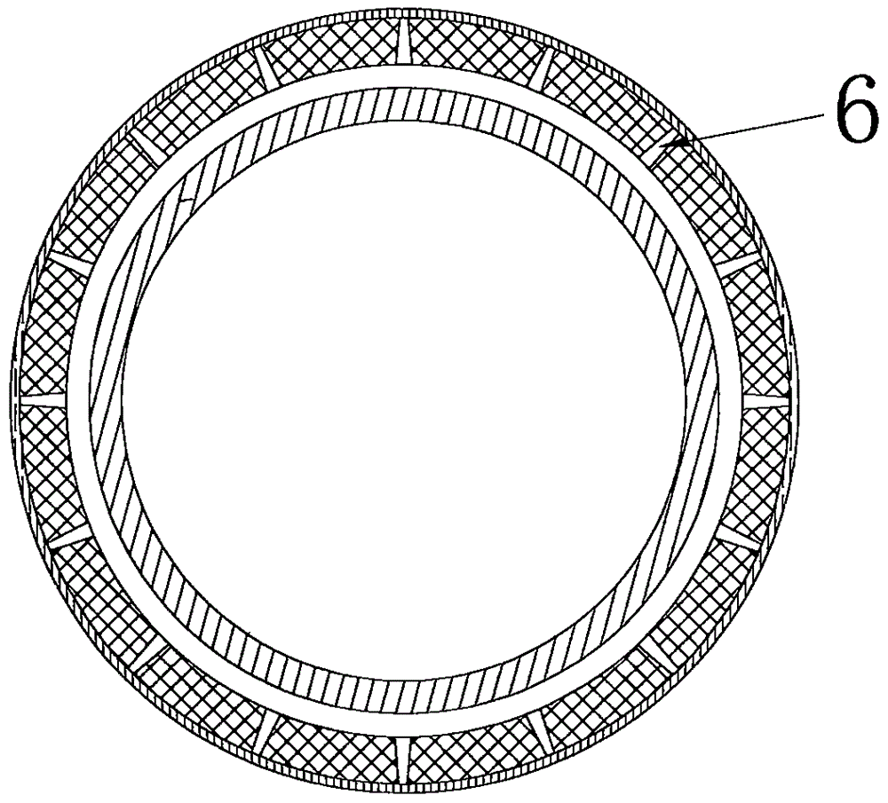
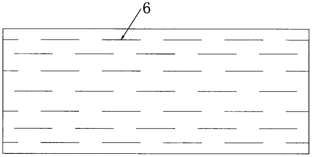
[0014] Such as figure 1 , figure 2 and image 3 As shown, it is the front sectional view, the side view sectional view and the front view of the metal foam sand control layer in the patent of the present invention, which includes the outer tube protective sleeve 1, the metal foam sand control layer 2, the wire-wrapped support strip 3, and the base pipe 4. Diversion holes 5 and diversion seams 6. The feature of the patent of the present invention is that its structure includes from the outside to the inside: the outer tube protective sleeve, the metal foam sand control layer, the wire wrapping support strip, and the base pipe. The diversion seam is a trapezoidal seam with a narrow outside and a wide inside. The wire-wound support strips are welded outside the base pipe, and the base pipe contains parallel diversion holes, each of which is located between two winding holes. In the middle of the wire support bar.

[0015] The unexplained parts involved in the patent of the p...


PUM


Abstract

The invention relates to a novel foam metal sand-prevention pipe. The sand-prevention pipe is used for underground sand prevention for an oil and gas field and structurally comprises an outer pipe protective casing, a foam metal sand-prevention layer, wire-winding support strips and a base pipe in sequence from outside to inside, the foam metal sand-prevention layer is provided with flow guide gaps which are distributed in a staggered mode, each flow guide gap is in a trapezoidal shape with the outside narrow and the inside wide, the wire-winding support strips are welded to the outside of the base pipe, the base pipe contains parallel flow guide through holes, each flow guide through hole is located between the corresponding two wire-winding support strips, the minimum filtration diameter of the foam metal sand-prevention layer reaches 0.05 mm, the thickness of the foam metal sand-prevention layer is 0.5-1 cm, and the gap width, at the narrowest position, of each flow guide gap is greater than or equal to 01mm. The novel foam metal sand-prevention pipe is good in permeability and high in strength, each flow guide gap with the outside narrow and the inside wide has the self-cleaning function, by means of the sand-prevention pipe, sand-prevention precision is greatly improved, the service life of the sand-prevention pipe is greatly prolonged, good flow guide capability is achieved, and the liquid flow is effectively increased.

Description

technical field [0001] The patent of the invention belongs to the field of petroleum and natural gas, and specifically relates to a novel foam metal sand control pipe. Background technique [0002] During the oil production process, due to geological factors and production reasons, the sand in the oil layer will flow into the well together with the oil and gas, and the bottom of the well will be blocked. In view of this situation, the mechanical sand control method is widely used in oil fields, that is, sand control pipes are placed in the oil layer. At present Commonly used sand control pipes include slotted liners, wire-wound screens, multi-layer metal mesh wound composite screens, etc. After investigation, these sand control pipes have the following disadvantages: low permeability, resulting in poor flow conductivity, and cannot effectively improve the flow rate of liquid. The flow rate is increased, the oil production rate is increased, and the filtration accuracy is not...

Claims


Application Information

Patent Timeline
Patent Type & Authority Applications(China)
IPC IPC(8): E21B43/08
Inventor 汪伟
Owner CHINA UNIV OF PETROLEUM (BEIJING)
Why Eureka
Try Eureka