Oil-gas separator on motorcycle engine tank body

A technology of oil and gas separator and oil and gas separation chamber, which is applied in the direction of engine components, machines/engines, mechanical equipment, etc., can solve the problems of large cylinder head vibration, high cylinder head thermal load, labyrinth failure, etc., to achieve good oil and gas separation effect, The overall structure is simple and the manufacturing cost is low.

Active Publication Date: 2016-01-06
浙江美可达摩托车有限公司
View PDF9 Cites 0 Cited by
  • Summary
  • Abstract
  • Description
  • Claims
  • Application Information

AI Technical Summary

Problems solved by technology

[0003] Under normal circumstances, the oil-gas separator arranged on the cylinder head cover needs to be disassembled or replaced related engine spark plugs and other parts of the motorcycle engine cylinder head cover, or the vibration of the cylinder head can easily lead to a decrease in the labyrinth seal.
In addition, the cylinder head has a high thermal load, which greatly increases the probability of rubber or plastic sealing failure, which leads to the failure of the entire labyrinth.
Therefore, under normal circumstances, the cost and material selection requirements of the labyrinth oil-gas separator arranged on the cylinder head cover are relatively high, resulting in an increase in production costs, and maintenance is required after a period of use, which also increases the use cost.

Method used


Image

  • Oil-gas separator on motorcycle engine tank body
  • Oil-gas separator on motorcycle engine tank body
  • Oil-gas separator on motorcycle engine tank body

Examples


Embodiment Construction

[0022] The following are specific embodiments of the present invention and in conjunction with the accompanying drawings, the technical solutions of the present invention are further described, but the present invention is not limited to these embodiments.

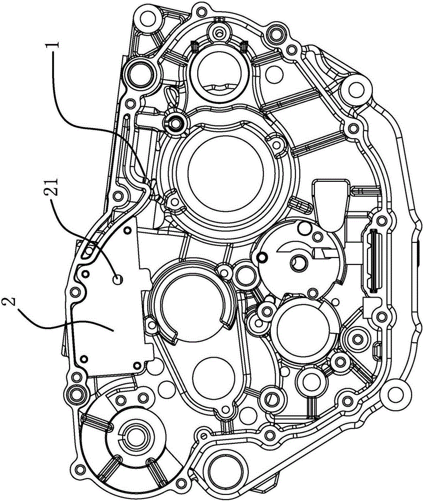
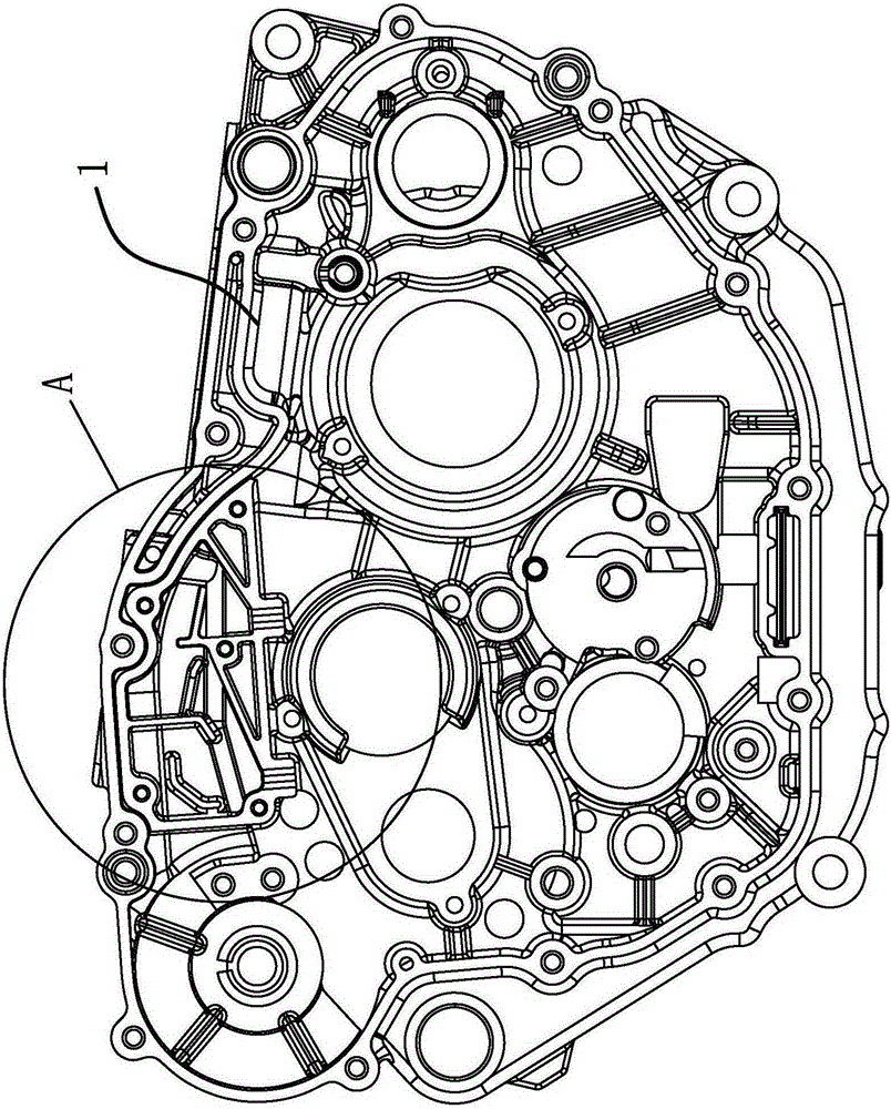
[0023] Such as figure 1 and figure 2 As shown, the motorcycle engine case includes a vertically arranged case cover 1, and the oil-air separator on the motorcycle engine case is arranged on the inside of the case cover 1, and the oil-air separator includes an end cover 2 and an annular coaming plate 3 , the coaming 3 is integrally formed with the tank cover 1, one end of the coaming 3 is fixed to the inner wall of the tank cover 1, an oil-gas separation chamber 4 is formed between the coaming 3 and the inner wall of the tank cover 1, and the other end of the end cover 2 and the coaming 3 One end is fixed and can seal the oil-gas separation chamber 4 .

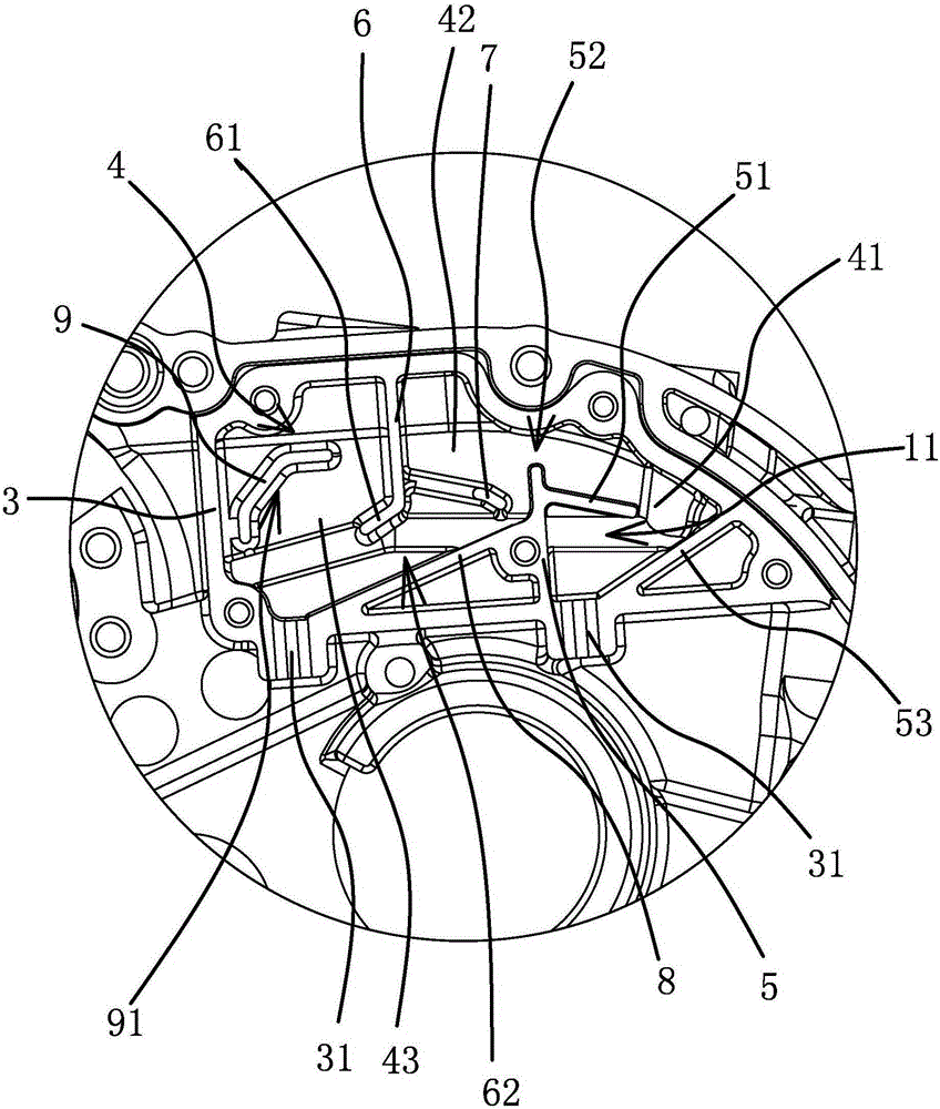
[0024] Such as image 3 and Figure 4 As shown, the first partiti...


PUM


Abstract

The invention provides an oil-gas separator on a motorcycle engine tank body, and belongs to the technical field of motorcycles. The technical problem that because oil-gas separation can not be achieved until an independent oil-gas separator is fixed to a tank body of an existing motorcycle, the structure is complex is solved. The engine tank body comprises a vertical tank cover. The oil-gas separator is arranged inside the tank cover, and comprises an end cover and a surrounding plate. The surrounding plate and the tank cover are fixed to form an oil-gas separation cavity. A first separation plate and a second separation plate are fixed to the inner side of the surrounding plate and divide the oil-gas separation cavity into a first separation cavity body, a second separation cavity body and a third separation cavity body which are sequentially arrayed. A steam inlet is formed in the end cover. When the end cover is fixed to the other end of the surrounding plate, the steam inlet of the end cover is communicated with the first separation cavity; two oil return openings are formed in the lower portion of the surrounding plate, and a gas outlet is formed in the upper portion of the surrounding plate. The oil-gas separator has the advantages of being good in oil-gas separation effect and simple in structure.

Description

technical field [0001] The invention belongs to the technical field of motorcycles, and relates to an oil-gas separator on a motorcycle engine case. Background technique [0002] The oil-gas separator of existing motorcycle engine generally adopts labyrinth type oil-gas separator to realize, and labyrinth type oil-gas separator is connected in the cylinder head cover of motorcycle engine as independent parts. [0003] Usually, the oil-gas separator arranged on the cylinder head cover, because the motorcycle engine cylinder head cover needs to be disassembled or replaced related engine spark plugs and other parts, or the vibration of the cylinder head will easily lead to the decrease of the labyrinth seal. In addition, the cylinder head has a high thermal load, which greatly increases the probability of rubber or plastic sealing failure, which leads to the failure of the entire labyrinth. Therefore, under normal circumstances, the cost and material selection requirements of ...

Claims


Application Information

Patent Timeline
Patent Type & Authority Applications(China)
IPC IPC(8): F01M13/04
Inventor 林树军蔡良正陈礼信龚建平
Owner 浙江美可达摩托车有限公司
Why Eureka
Try Eureka