
Standing tension spring shaft

A technology of bearings and bodies, applied in the field of standing extension spring shafts, can solve the problems of high manufacturing costs, achieve the effects of reduced manufacturing materials, perfect functions, and superior flexibility

Inactive Publication Date: 2016-01-06
陆如癸
View PDF0 Cites 0 Cited by
  • Summary
  • Abstract
  • Description
  • Claims
  • Application Information

AI Technical Summary

Problems solved by technology

[0002] In the prior art, as a device in the car, the station frame needs to be fixed with a tension spring shaft, but the tension spring shaft in the prior art is usually made of solid materials, which has the disadvantage of high manufacturing cost

Method used


Image

  • Standing tension spring shaft

Examples


Embodiment Construction

[0010] The present invention will be further described in detail below in conjunction with the accompanying drawings and specific embodiments.

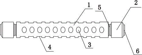
[0011] see figure 1 , a standing extension spring shaft, including a bearing body 1, in this embodiment, the bearing body 1 is a hollow structure, the bearing body 1 has a number of through holes 3, and a number of annular grooves 4 are opened around the bearing body 1 , in this embodiment, the annular groove 4 is arranged along the length direction of the bearing body 1, and the spacing between the annular grooves 4 is the same, and the two ends of the bearing body 1 are respectively connected with a bearing head 2 through an elastic member 5. In this embodiment , the elastic member 5 is a spring, and the elastic member 5 is provided with a connecting head 6 at the end of the spring bearing head 2 away from the bearing body 1 .

[0012] The present invention has superior flexibility through the improvement of the structure, and save...


PUM


Abstract

The invention discloses a standing tension spring shaft. The standing tension spring shaft comprises a bearing body in which a plurality of through holes are formed; a plurality of annular grooves are peripherally formed in the bearing body; each of the two ends of the bearing body is connected with a bearing head through an elastic element; a connector is arranged on the end portion, far away from the bearing body, of each bearing head. Compared with the prior art, the standing tension spring shaft is capable of saving more manufacturing material, and is more flexible.

Description

technical field [0001] The invention relates to a standing auxiliary tool, in particular to a standing extension spring shaft. Background technique [0002] In the prior art, as a device in the car, the station frame needs to be fixed by a tension spring shaft. However, the tension spring shaft in the prior art is usually made of solid material, which has the disadvantage of high manufacturing cost. Contents of the invention [0003] Aiming at the shortcomings of the above-mentioned prior art, the present invention provides a standing extension spring shaft, which effectively solves the above-mentioned problems in the prior art. [0004] In order to achieve the above object, the technical solution adopted by the present invention is: a standing extension spring shaft, including a bearing body, a number of through holes are opened on the bearing body, and a number of annular grooves are opened around the bearing body, and the two ends of the bearing body are passed through ...

Claims


Application Information

Patent Timeline
IPC IPC(8): F16C27/00
Inventor 陆如癸
Owner 陆如癸
Learn More