Both-way damping adjustable shock absorber

A two-way damping and shock absorber technology, applied in the direction of shock absorbers, springs/shock absorbers, shock absorbers, etc., can solve the problem of inability to adapt to different road conditions, poor shock absorption effect, and unadjustable shock absorption strength of shock absorbers And other issues

Inactive Publication Date: 2016-01-06
AXR CHINA INC
View PDF10 Cites 1 Cited by
  • Summary
  • Abstract
  • Description
  • Claims
  • Application Information

AI Technical Summary

Problems solved by technology

And the existing shock absorber consists of a cylinder body, a piston located in the cylinder body, a piston rod whose inner end is connected to the piston, a bottom valve located at the bottom of the cylinder body, a top valve located at the top of the cylinder body, and a piston rod located at the cylinder body top. The bottom co

Method used


Image

  • Both-way damping adjustable shock absorber
  • Both-way damping adjustable shock absorber
  • Both-way damping adjustable shock absorber

Examples


Embodiment 1

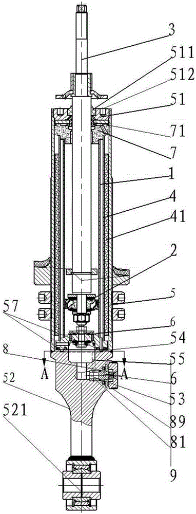
[0014] Such as figure 1 , Figure 4 As shown, the two-way damping adjustable shock absorber includes a working cylinder 1, a piston 2 disposed in the working cylinder 1, a piston rod 3 whose inner end is connected to the piston 2, an oil return pipe 4 sleeved outside the working cylinder 1, and a sleeve The oil storage cylinder 5 arranged outside the oil return pipe 4, the bottom of the working cylinder 1 and the oil return pipe 4 is provided with a bottom valve 6, the upper end of the working cylinder 1 and the oil return pipe 4 is provided with a guide 7, and the oil storage The upper end of the barrel 5 is provided with a fastening cover 51, and the lower end of the oil storage barrel 5 is provided with a bottom cover 52, which is characterized in that a mechanically adjustable knob 8 is provided on one side of the bottom cover 52, and a Adjustment hole 53, the mechanically adjustable knob 8 is installed in the adjustment hole 53, the joint end of the bottom cover 52 and t...

Embodiment 2

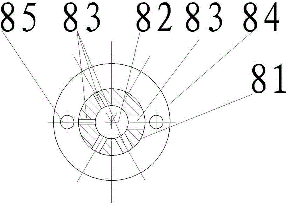
[0016] Such as figure 1 , figure 2 , image 3 , Figure 4 As shown, the mechanically adjustable knob 8 includes an adjustment column 81 installed in the adjustment hole 53. The inner end of the adjustment column 81 is hollow and is an adjustment chamber 82. The side walls of the adjustment chamber 82 are provided with different diameters. A flow hole 83, the flow hole 83 corresponds to the adjustment hole 53, the adjustment column 81 is provided with a retaining ring 84, the retaining ring 84 is provided with a steel ball hole 85, the joint surface of the bottom cover 52 and the retaining ring 84 Steel ball slot 55 is provided on the top, steel ball 86 is installed in 88 of said steel ball hole 85, and butterfly spring 87 is arranged on the outside of said retaining ring 84, and said butterfly spring 87 acts on steel ball 86, and said butterfly spring The outside of 87 is provided with a T-shaped block 88, and the T-shaped block 88 is set on the outer end of the adjustment...

Embodiment 3

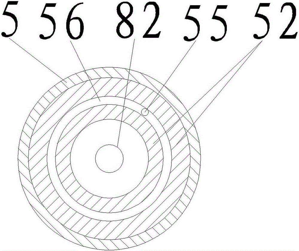
[0018] Such as figure 1 , figure 2 , Figure 4 As shown, the oil return pipe 4 is covered with a foam layer 41, the upper end of the guide 7 is provided with an oil seal 71, the bottom cover 52 is connected with a suspension ring 521, and the fastening cover 51 is connected to the inner wall of the upper end of the oil storage cylinder 4. For screw fit, the end face of the fastening cover 51 is provided with two clamping holes 511 for installing the fastening cover 51, and the middle part of the fastening cover 51 is provided with a sealing ring 512, and the sealing ring sleeve 512 is arranged on the piston rod 3 superior. When working, the hydraulic oil of the working cylinder 1 enters the oil return cavity between the oil return pipe 4 and the working cylinder 1, then enters the oil collection tank 56, and then flows through the connecting channel 55, the regulating hole 53, and the regulating chamber 82 of the regulating column 81. The bottom valve 6 returns to the work...


PUM


Abstract

The invention relates to the field of automobile accessories, and in particular to a both-way damping adjustable shock absorber. The both-way damping adjustable shock absorber comprises a work cylinder, a piston arranged in the work cylinder, a piston rod with the inner end connected with the piston, an oil returning pipe arranged outside the work cylinder in a sleeving manner, and an oil storage barrel arranged on the outer side of the oil returning pipe in a sleeving manner. A bottom valve is arranged at the bottom of the work cylinder and the bottom of the oil returning pipe. A guiding device is arranged at the upper end of the work cylinder and the upper end of the oil returning pipe. A fastening cover is arranged at the upper end of the oil storage barrel. A bottom cover is arranged at the lower end of the oil storage barrel. The both-way damping adjustable shock absorber is characterized in that a mechanical adjustable rotary knob is arranged on one side of the bottom cover, an adjusting hole is formed in the bottom cover, and the mechanical adjustable rotary knob is arranged in the adjusting hole; and an oil collecting trough is formed in the combination end of the bottom cover and the bottom valve, and a connecting channel for the adjusting hole and the oil collecting trough to be communicated is arranged in the bottom cover. The damping strength of the shock absorber can be adjusted, the both-way damping adjustable shock absorber can adapt to different road conditions and is good in damping effect and simple in structure, and the damping performance can be adjusted according to different road conditions.

Description

technical field [0001] The invention relates to an automobile shock absorber, in particular to a two-way damping adjustable shock absorber. Background technique [0002] In recent years, with the rapid development of the automobile industry, especially the car industry, shock absorbers, which are important parts of automobiles, have also developed rapidly. Automobile shock absorber is a kind of damping element and one of the important components of automobile suspension system, which plays a decisive role in the ride comfort, comfort, safety, steering operability and passability of the vehicle. And the existing shock absorber consists of a cylinder body, a piston located in the cylinder body, a piston rod whose inner end is connected to the piston, a bottom valve located at the bottom of the cylinder body, a top valve located at the top of the cylinder body, and a piston rod located at the cylinder body top. The bottom cover at the bottom of the body, the support rod, and t...

Claims


Application Information

Patent Timeline
IPC IPC(8): F16F9/44F16F9/19
Inventor 黄衍国黄小火
Owner AXR CHINA INC
Why Eureka
Try Eureka