Energy-saving stove base

A technology of energy-saving stoves and fixed steps, which is applied to stoves/stove bases and other directions, can solve the problems of unstable quality and heavy weight of ordinary stoves, and achieve the effects of reducing total cost, convenient and quick ash removal, and weight reduction.

Inactive Publication Date: 2016-01-06
侯国山
View PDF3 Cites 0 Cited by
  • Summary
  • Abstract
  • Description
  • Claims
  • Application Information

AI Technical Summary

Problems solved by technology

[0003] In order to solve the problems of heavy weight and unstable qualit

Method used


Image

  • Energy-saving stove base
  • Energy-saving stove base
  • Energy-saving stove base

Examples


Embodiment Construction

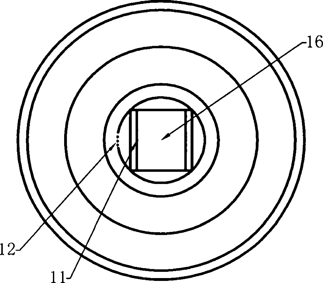
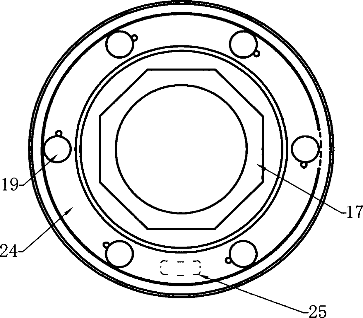
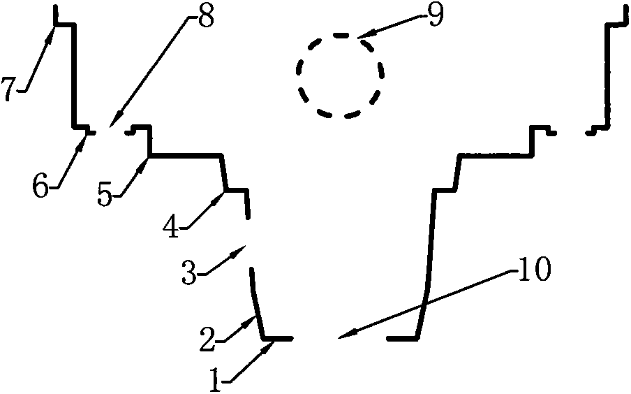
[0024] figure 1 , figure 2 A structural form of an energy-saving stove base is described. An energy-saving stove base, mainly composed of specific multi-level steps, the first fixed step of waste heat recovery device 7, the first fixed step of ash board 6, the first fixed step of refractory furnace core 5, the first fixed step of stove grate 4 , circle-quadrilateral transition section 2, the first slag plate fixed steps 1 are connected together to form the first energy-saving cooker base; the appearance of the first energy-saving cooker base is stepped cylindrical, or stepped prismatic, or stepped circular frustum , or stepped prism shape; the base of the first energy-saving stove has a first air inlet 3; the first row of ash board fixed steps 6 has a first row of ash holes 8; the upper part of the first energy-saving stove base has a first smoke outlet 9 There is a first slag hole 10 on the first slag plate fixed step 1; the first waste heat recovery device fixed step 7, t...


PUM


Abstract

An energy-saving stove base is mainly composed of specific multistage steps. By using the energy-saving stove base on a stove, an original manual production process of the stove can be changed to be a part assembly production process, so that the weight of the stove is reduced, the quality of the stove is stable and the total cost of the stove is reduced. Ash discharge holes in ash discharge plate fixing steps cooperate with ash discharge holes in an ash discharge plate, so that ash discharge becomes convenient and rapid. The energy-saving stove base is long in service life and simple in production process, can be industrially produced on a large scale and has a wide market prospect.

Description

Technical field [0001] The invention relates to a cooker base, in particular to an energy-saving cooker base. Background technique [0002] At present, all parts of the cooker are fixed on the bottom frame of the angle iron tailor-welded bracket by refractory materials, which not only increases the weight of the cooker, but also makes it difficult to accurately locate the positions of the parts, which makes it difficult to guarantee the quality of the cooker. Contents of the invention [0003] In order to solve the problems of heavy weight and unstable quality of ordinary cookers, the invention provides an energy-saving cooker base. [0004] The technical solution adopted by the present invention to solve the technical problem is: an energy-saving stove base, which is mainly composed of specific multi-level steps, the first fixed step of the waste heat recovery device, the fixed step of the first row of ash plates, and the fixed step of the first refractory furnace core. ...

Claims


Application Information

Patent Timeline
IPC IPC(8): F24C15/08
Inventor 侯国山
Owner 侯国山
Why Eureka
Try Eureka