
Electric heating device

An electric heating device and electric heating tube technology, applied in the field of heaters, can solve problems such as inconvenient installation, waste of resources, and unfavorable air circulation

Inactive Publication Date: 2016-01-06
ZHEJIANG GIANT TECH CO LTD
View PDF8 Cites 1 Cited by
  • Summary
  • Abstract
  • Description
  • Claims
  • Application Information

AI Technical Summary

Problems solved by technology

Traditional heat sinks are all in one series. Multiple larger sheet structures are integrally formed and fixedly connected. It is inconvenient to install. In case some parts are damaged, they can only be replaced as a whole. Addition, reduction and maintenance are inconvenient and costly. To a certain extent, it causes a waste of resources
Moreover, many heat dissipation holes on the heat sink in the prior art are square. During the air circulation process of the square holes, eddy currents are likely to be generated at the corners of the square holes, which is not conducive to air circulation.

Method used


Image

  • Electric heating device
  • Electric heating device

Examples


Embodiment Construction

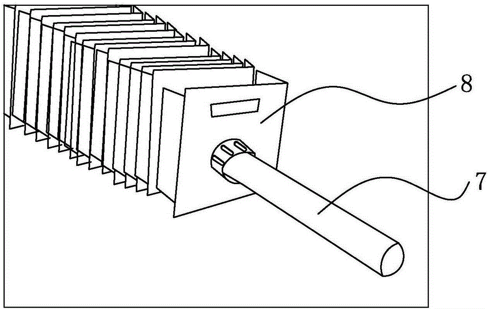
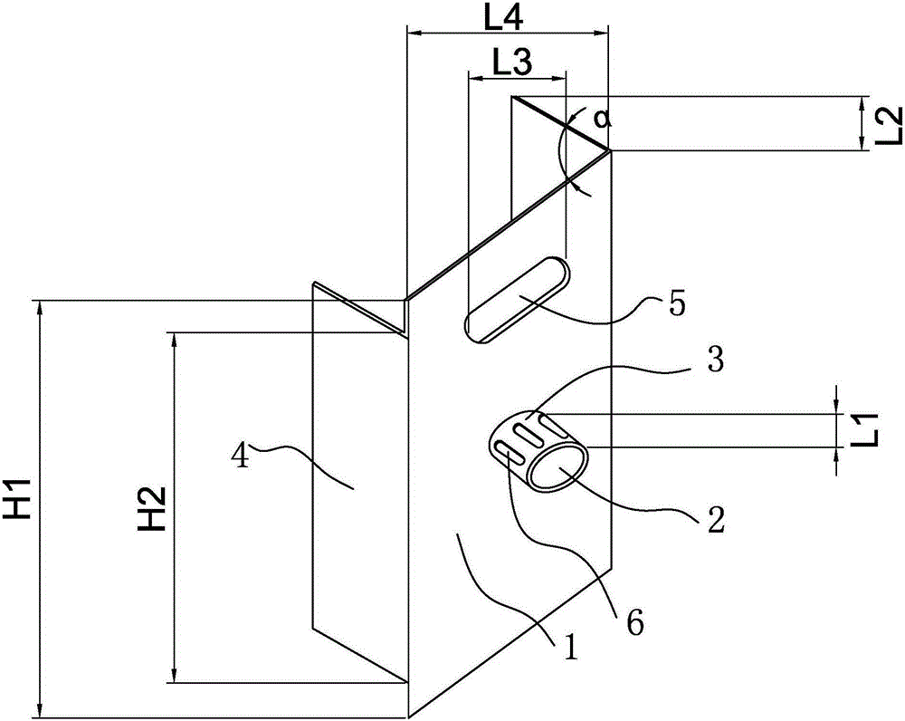
[0013] Such as Figure 1-2 As shown, the electric heating device includes an electric heating tube 7 and a heat sink 8. The heat sink 8 includes a main body 1 of a sheet metal structure, a through hole 2 is opened in the middle of the main body, a flange 3 is provided on the edge of the through hole, and flanges are also provided on both sides of the main body. 4. The direction of the flange 4 is opposite to that of the flange 3 . A plurality of cooling fins are sleeved and installed on the electric heating tube 7 through the through hole 7 to realize heating and heat dissipation. Combined with the length of the flange 3 and the length of the flange 4, the distance between the two heat sinks on the electric heating tube can be determined. Only when the diameter of the through hole and the flange is larger than the diameter of the electric heating tube installed by the cooling fin can it be socketed on the electric heating tube.

[0014] The turning angle α between the flange ...


PUM


Abstract

An electric heating device comprises an electric heating tube and a plurality of cooling fins connected onto the electric heating tube in a sleeving manner, wherein the cooling fin main body is planar sheet metal; revers are arranged on two symmetrical side edges of the cooling fin main body; a through hole is formed in the middle of the cooling fin main body; a flange is arranged on the through hole; the direction of the revers is opposite to that of the flange; the diameter of the flange is greater than that of the electric heating tube. The electric heating device adopts the independent cooling fins mounted on the electric heating tube in a sleeving manner to realize heat dissipation, is high in warming efficiency and very convenient to dismount, mount, repair and replace, can be used independently, and also can be mounted on other warming equipment.

Description

technical field [0001] The invention belongs to the field of heaters, and mainly refers to an electric heating device. Background technique [0002] The heating radiator mainly plays the role of heat conduction for heat dissipation. When the heat medium with high temperature flows through the radiator, the heat carried by the heat medium is continuously transferred to the object with a lower temperature through the radiator, so as to realize the heat dissipation. temperature transfer. Traditional heat sinks are all in one series. Multiple larger sheet structures are integrally formed and fixedly connected. It is inconvenient to install. In case some parts are damaged, they can only be replaced as a whole. Addition, reduction and maintenance are inconvenient and costly. To a certain extent, it causes waste of resources. Moreover, in the prior art, many heat dissipation holes on the heat sink are square, and during the air circulation process of the square holes, eddy curren...

Claims


Application Information

Patent Timeline
IPC IPC(8): F24D13/02F24D19/02
Inventor 闵大伟
Owner ZHEJIANG GIANT TECH CO LTD
Learn More