Laying construction method of drainage pipeline for sewage disposal

A technology for drainage pipelines and sewage treatment, which is used in pipeline laying and maintenance, mechanical equipment, pipes/pipe joints/pipe fittings, etc. , the effect of precise location

Inactive Publication Date: 2020-07-28
李胜成
View PDF0 Cites 2 Cited by
  • Summary
  • Abstract
  • Description
  • Claims
  • Application Information

AI Technical Summary

Problems solved by technology

[0004] Aiming at the problems in the prior art, the object of the present invention is to provide a construction method for laying drainage pipes for sewage treatment, which solves the problem that the laying of drainage pipes requires a lot of work time due to the large diameter and heavy weight of the drainage pipes. The operation is difficult, and the drainage pipe is difficult to accurately place the technical problem in the foundation pit

Method used


Image

  • Laying construction method of drainage pipeline for sewage disposal
  • Laying construction method of drainage pipeline for sewage disposal
  • Laying construction method of drainage pipeline for sewage disposal

Examples


Embodiment 1

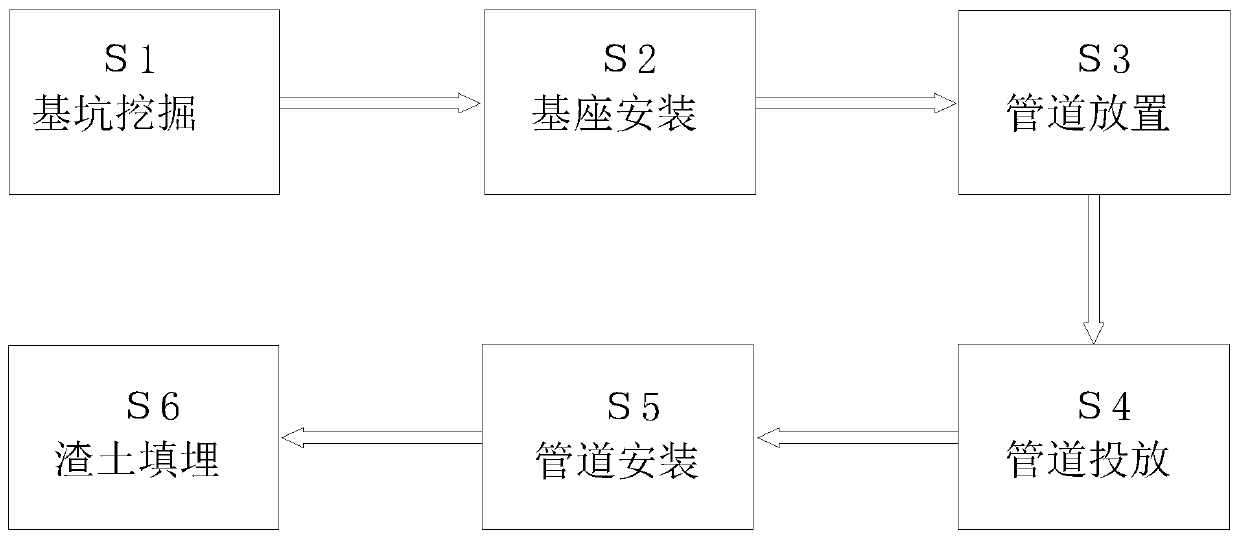
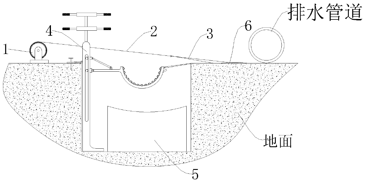
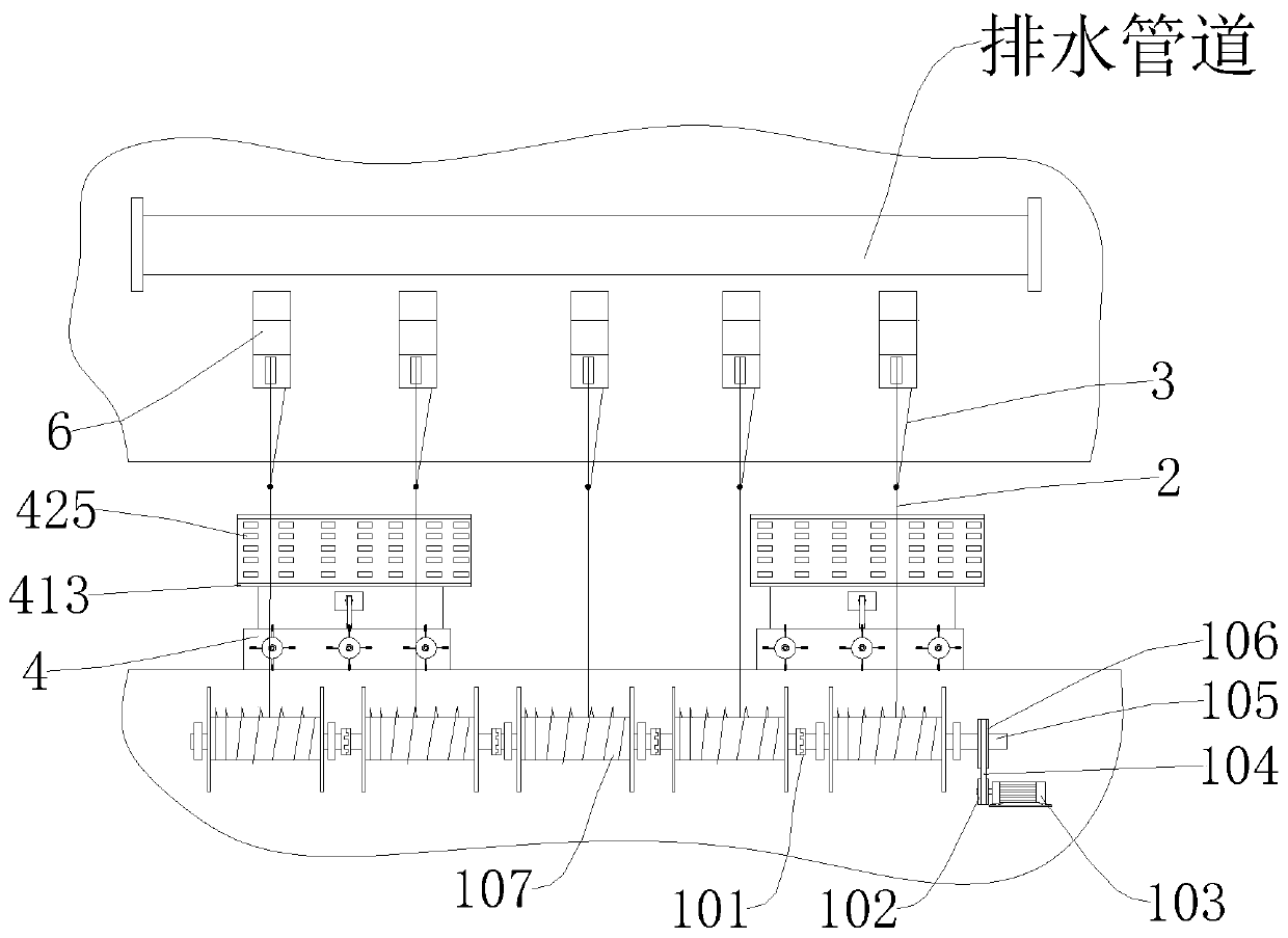
[0044] see Figure 1-7 , which is a schematic diagram of the overall structure of a construction method for laying drainage pipes for sewage treatment;

[0045] A construction method for laying drainage pipes for sewage treatment, comprising the following steps:

[0046] S1. Foundation pit excavation: Excavate a foundation pit for laying drainage pipes on the ground where the sewage flows. The opening of the foundation pit faces upward, and the side wall of the foundation pit is perpendicular to the bottom surface of the foundation pit;

[0047] S2. Base installation: place bases 5 for supporting drainage pipes in the foundation pit excavated in step S1, place multiple bases 5, and fix the two adjacent bases 5 on the bottom of the foundation pit at equal intervals ;

[0048] S3, pipeline placement: place the drainage pipeline for laying near the foundation pit that has been excavated in step 1, and place the axis of the drainage pipeline to be parallel to the side wall of th...

Embodiment 2

[0068] The content of this embodiment is the same as that of the above-mentioned embodiment 1, and the specific similarities will not be elaborated in this embodiment, and the specific differences are:

[0069] see figure 1 , figure 2 or image 3 , which is a schematic diagram of the overall structure of another construction method for laying drainage pipes for sewage treatment;

[0070] A construction method for laying drainage pipes for sewage treatment, comprising the following steps:

[0071] S1. Foundation pit excavation: Excavate a foundation pit for laying drainage pipes on the ground where the sewage flows. The opening of the foundation pit faces upward, and the side wall of the foundation pit is perpendicular to the bottom surface of the foundation pit;

[0072] S2. Base installation: place bases 5 for supporting drainage pipes in the foundation pit excavated in step S1, place multiple bases 5, and fix the two adjacent bases 5 on the bottom of the foundation pit a...


PUM


Abstract

The invention discloses a laying construction method of a drainage pipeline for sewage disposal, relates to the technical field of sewage discharge, and in particular relates to a laying constructionmethod of the drainage pipeline for sewage disposal. The method comprises the following steps: S1, excavating a foundation pit, namely, excavating the foundation pit for laying the drainage pipeline on the ground through which sewage flows, wherein the opening of the foundation pit faces upwards, and the side wall of the foundation pit is perpendicular to the bottom surface of the foundation pit;and S2, mounting bases, namely, placing the bases used for supporting the drainage pipeline in the foundation pit excavated in the step S1, wherein a plurality of bases are placed, and every two adjacent bases are fixed to the bottom face of the foundation pit at equal intervals. A guide plate is fixed to the top end of each tray, each guide plate is arranged to be of a square-block-shaped flat plate structure, the top end of each guide plate is erected on the ground on the other side of the foundation pit, so that the drainage pipeline can roll to the side wall edge of the foundation pit conveniently, and the drainage pipeline rolls into the trays through guiding of the guide plates.

Description

technical field [0001] The invention relates to the technical field of sewage discharge, in particular to a drainage pipe laying construction method for sewage treatment. Background technique [0002] Sewage refers to the discharged water from life and production that is polluted to a certain extent, and the water that has lost its original function is called sewage for short. It is mainly the water after daily use, which contains more organic matter and is easier to treat. The existing, whether it is rural or urban, has a huge amount of domestic wastewater discharged every day. For urban or rural densely populated places, wastewater is difficult to It is directly used, so it is necessary to use drainage pipes to transport wastewater from densely populated places to another, so as to facilitate the unified purification and utilization of wastewater. [0003] Drainage pipeline refers to the system composed of pipes and channels and their ancillary facilities for collecting a...

Claims


Application Information

Patent Timeline
Patent Type & Authority Applications(China)
IPC IPC(8): F16L1/036F16L1/06B66F19/00
CPCB66F19/00F16L1/036F16L1/06
Inventor 李胜成
Owner 李胜成
Why Eureka
Try Eureka