
Monitoring system and method of ring main unit

A technology of monitoring system and ring network cabinet, which is applied in the field of electric power, can solve the problems of inaccurate monitoring and low accuracy of signal acquisition, and achieve the effects of current measurement, fault current detection, and temperature monitoring and alarm integration

Inactive Publication Date: 2016-01-06
STATE GRID BEIJING ELECTRIC POWER +1
View PDF5 Cites 5 Cited by
  • Summary
  • Abstract
  • Description
  • Claims
  • Application Information

AI Technical Summary

Problems solved by technology

[0004] Embodiments of the present invention provide a monitoring system and method for a ring network cabinet, so as to at least solve the technical problems of low signal acquisition accuracy and inaccurate monitoring of the ring network cabinet monitoring system in the related art

Method used


Image

  • Monitoring system and method of ring main unit
  • Monitoring system and method of ring main unit
  • Monitoring system and method of ring main unit

Examples


Embodiment 1

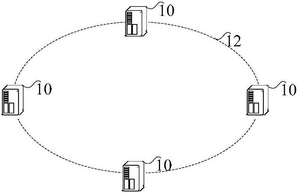
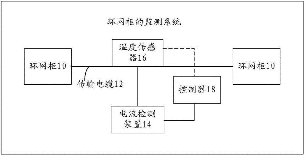
[0027] figure 1 It is a schematic diagram of a ring network cabinet according to the prior art; figure 2 It is a schematic structural diagram of a monitoring system of a ring network cabinet according to Embodiment 1 of the present invention, combined with figure 1 with figure 2 As shown, the monitoring system includes: ring main unit 10, transmission cable 12, current detection device 14, temperature sensor 16 and controller 18, wherein:

[0028] The transmission cable connected to the ring main unit is used to transmit current.

[0029] The current detection device is connected with the transmission cable, and is used for detecting the current value of the current, and generating fault information indicating that the transmission cable fails according to the current value.

[0030] The temperature sensor is arranged on the transmission cable and connected with the current detection device, and is used for detecting the temperature of the transmission cable.

[0031] Sp...

Embodiment 2

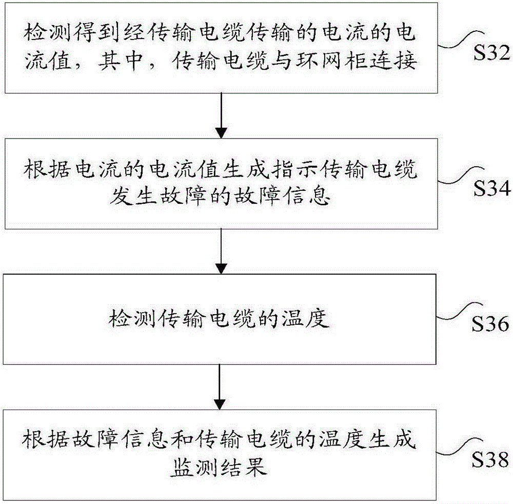
[0051] According to an embodiment of the present invention, a method embodiment of a monitoring method for a ring network cabinet is provided. It should be noted that the steps shown in the flow chart of the accompanying drawings can be executed in a computer system such as a set of computer-executable instructions , and, although a logical order is shown in the flowcharts, in some cases the steps shown or described may be performed in an order different from that shown or described herein.

[0052] image 3 It is a flow chart of a monitoring method for a ring network cabinet according to Embodiment 2 of the present invention, such as image 3 As shown, the method includes the following steps:

[0053] Step S32, detecting the current value of the current transmitted through the transmission cable, wherein the transmission cable is connected to the ring network cabinet;

[0054] Step S34, generating fault information indicating that the transmission cable is faulty according ...


PUM


Abstract

The invention discloses a monitoring system and method of a ring main unit. The monitoring system includes a transmission cable which is connected with the ring main unit and is used for transmitting current, a current detection device which is connected with the transmission cable and is used for detecting the current value of the current and generating fault information indicating a fault occurring on the transmission cable according to the current value, a temperature sensor which is arranged on the transmission cable and is connected with the current detection device, and is used for detecting the temperature of the transmission cable, and a controller which is connected with the current detection device and the temperature sensor respectively and is used for generating monitoring results according to the fault information and the temperature of the transmission cable. With the monitoring system and method of the invention adopted, technical problems of low signal acquisition precision and inaccurate monitoring of a monitoring system of a ring main unit in the prior art can be solved.

Description

technical field [0001] The invention relates to the field of electric power, in particular to a monitoring system and method for a ring network cabinet. Background technique [0002] Ring main unit has a wide range of applications in the field of power supply, and has played a very important role in the construction of urban power supply network. At present, there are no mature products for the comprehensive intelligent monitoring of ring network cabinets at home and abroad. The fault indicator used, the sensor cannot measure the current, and the fault judgment accuracy is low, the error is large, and the temperature indicator only detects the ambient temperature inside the cabinet. In the related art, the monitoring system of the ring network cabinet has low signal acquisition accuracy and inaccurate monitoring. [0003] For the above problems, no effective solution has been proposed yet. Contents of the invention [0004] Embodiments of the present invention provide a ...

Claims


Application Information

Patent Timeline
Patent Type & Authority Applications(China)
IPC IPC(8): G01R31/02
Inventor 王元杰周维刘庆时
Owner STATE GRID BEIJING ELECTRIC POWER
Learn More