Method and system for marking special processing figure in optical proximity correction

A technology of optical proximity effect and special processing, which is applied in photomechanical processing of originals, optics, and patterned surfaces for opto-mechanical processing. Effect

Active Publication Date: 2016-01-06
CSMC TECH FAB2 CO LTD
View PDF5 Cites 0 Cited by
  • Summary
  • Abstract
  • Description
  • Claims
  • Application Information

AI Technical Summary

Problems solved by technology

However, the marking layer provided by the customer often only covers part of the area of ​​the polygon, such as figure 2 As shown, resulting in the system misrecognition of the area covered by the undermark layer

Method used


Image

  • Method and system for marking special processing figure in optical proximity correction
  • Method and system for marking special processing figure in optical proximity correction
  • Method and system for marking special processing figure in optical proximity correction

Examples


Embodiment Construction

[0022] In order to make the object, technical solution and advantages of the present invention clearer, the present invention will be further described in detail below in conjunction with the accompanying drawings and embodiments. It should be understood that the specific embodiments described here are only used to explain the present invention, not to limit the present invention.

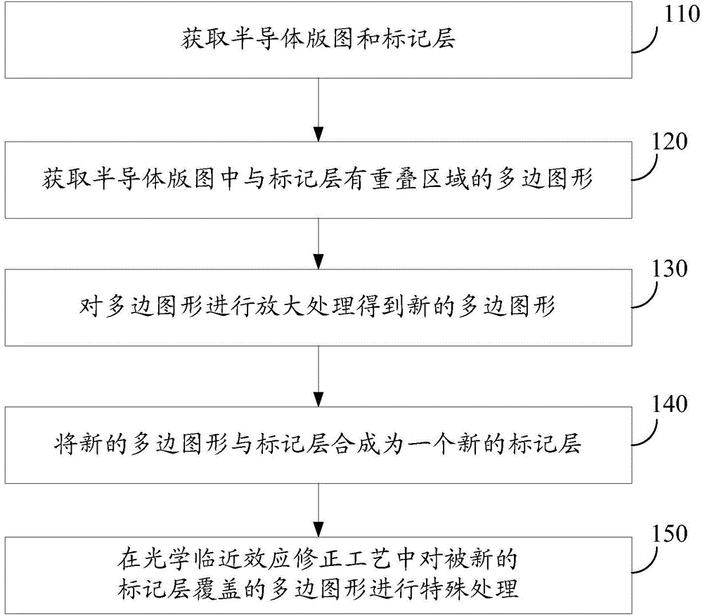
[0023] figure 1 Shown is a method for marking special processing graphics in optical proximity correction in an embodiment, including the following steps.

[0024] S110, acquiring a semiconductor layout and a marking layer.

[0025] In the semiconductor layout, when there is a region that needs to be specially designed, in order to realize the optical proximity correction (OPC), the region is specially treated, and the special region is often marked by adding a marking layer. Due to different requirements of different customers, the marking layer is generally provided by customers. However, the...


PUM


Abstract

The invention discloses a method for marking a special processing figure in optical proximity correction. The method comprises steps: a semiconductor pattern and a mark layer are obtained; a polygon, having an overlapping region with the mark layer, in the semiconductor pattern is obtained; the polygon is subjected to amplification processing and a new polygon is obtained; the new polygon and the mark layer are synthesized to a new mark layer; a polygon covered by the new mark layer is subjected to special processing in an optical proximity correction technology. The invention also discloses a system for marking a special processing figure in optical proximity correction. The polygon having an overlapping region with the mark layer, in the obtained semiconductor pattern is subjected to amplification processing, the processed polygon and the mark layer are synthesized to a new mark layer, the phenomenon that the mark layer only covers a part region of the polygon can be avoided, and burden cannot increased for the system.

Description

technical field [0001] The invention relates to the technical field of semiconductor preparation, in particular to a method and system for marking special processing graphics in optical proximity effect correction. Background technique [0002] In the semiconductor manufacturing process, when there is a specially designed area in the customer's layout, in order to implement OPC (Optical ProximityCorrection, optical proximity effect correction), the customer will add a layer of mark layer (marklayer) for special treatment of this area. This special area is marked. However, the marking layer provided by the customer often only covers part of the area of ​​the polygon, such as figure 2 As shown, thus causing the system to misidentify the area covered by the undermark layer. Contents of the invention [0003] Based on this, it is necessary to address the above problems and provide a method for marking specially processed graphics in the optical proximity effect correction in...

Claims


Application Information

Patent Timeline
Patent Type & Authority Applications(China)
IPC IPC(8): G03F1/36
Inventor 张雷王谨恒陈洁万金垠
Owner CSMC TECH FAB2 CO LTD
Why Eureka
Try Eureka