

Pulling-expanding type solar energy generator with functions of tilting and elevation
A technology of pull-out type and power generation device, which is applied in the direction of photovoltaic power generation, electrical components, and support structures of photovoltaic modules. Efficiency, effect of effective solar energy
- Summary
- Abstract
- Description
- Claims
- Application Information
AI Technical Summary
Problems solved by technology
Method used
Image

Examples
specific Embodiment approach 1
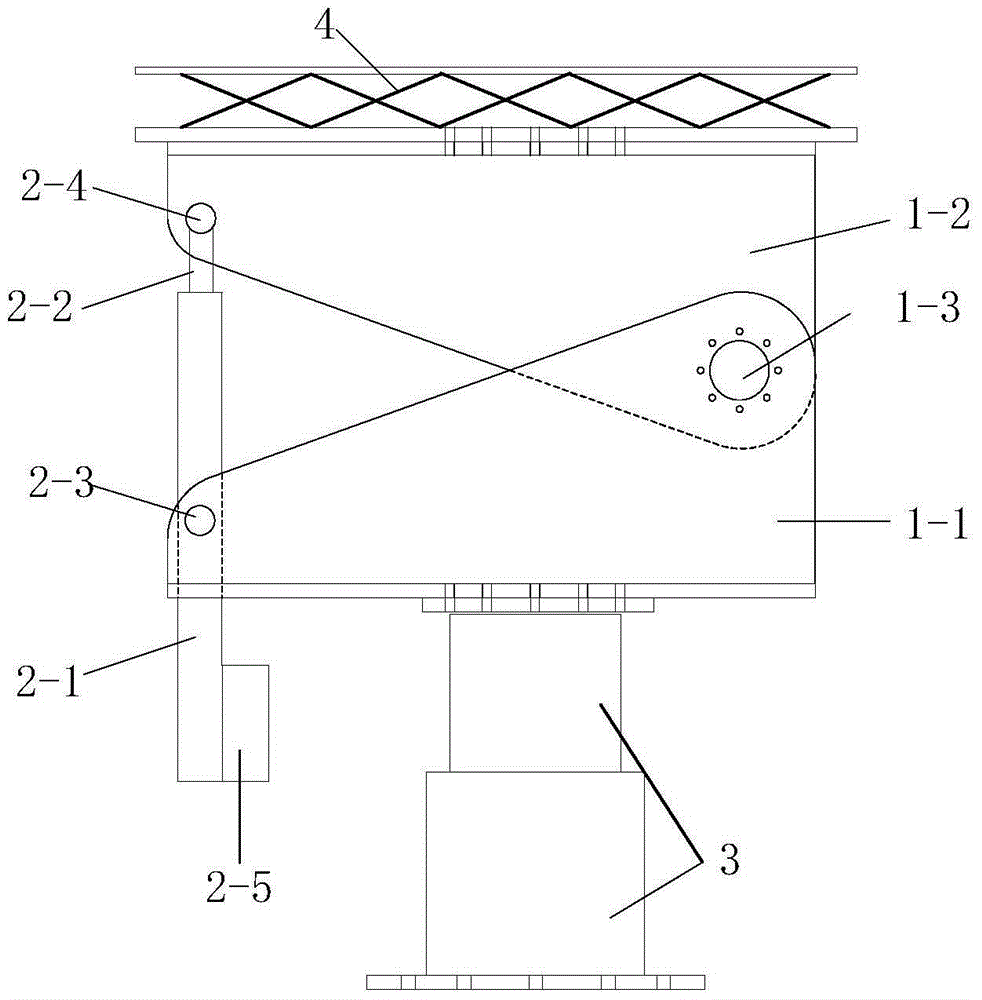
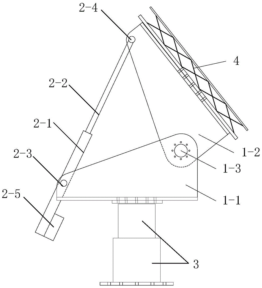
[0029] Specific embodiment one: the following combination Figure 1 to Figure 8 Describing this embodiment, the pull-out solar power generation device with tilting and lifting functions described in this embodiment includes a tilting mechanism, a telescopic mechanism, a lifting mechanism 3 and a pull-out solar panel mechanism 4;
[0030] The tilting mechanism includes a lower base 1-1, an upper base 1-2 and a tilting shaft 1-3;
[0031] The telescopic mechanism includes an outer casing 2-1, a telescopic rod 2-2, a static shaft 2-3, a moving shaft 2-4 and a drive motor 2-5;
[0032] The pull-out solar panel mechanism 4 includes an even number of solar panels 4-1, an outer support frame 4-2, an inner support frame 4-3, a panel accommodating truss 4-4, a steel cable 4-5, a reverse drive deceleration A motor 4-6, a pair of reverse wheels 4-7 and a support arm 4-8;
[0033] The upper surface of the lifting mechanism 3 is fixedly connected with the lower base 1-1. The lower base 1...
specific Embodiment approach 2
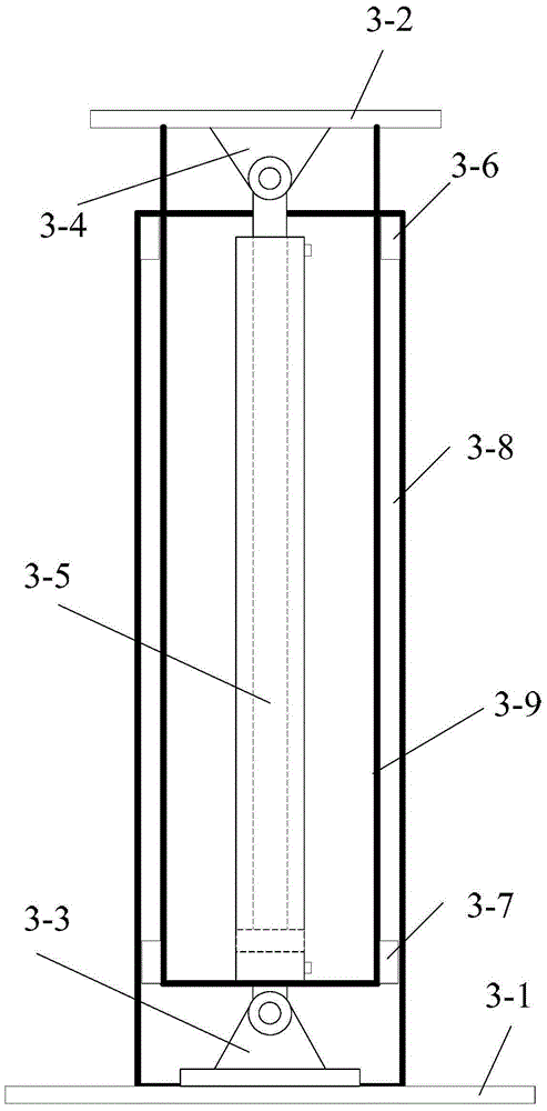
[0040] Specific embodiment two: the following combination image 3 and Figure 4 Describing this embodiment, this embodiment further describes Embodiment 1. The lifting mechanism 3 includes a lower flange 3-1, an upper flange 3-2, a lower cylinder base 3-3, an upper cylinder base 3-4, Oil cylinder 3-5, fixed slider 3-6, movable slider 3-7, outer support 3-8 and inner support 3-9,
[0041] The outer support body 3-8 is connected to the lower flange 3-1 through the lower oil cylinder base 3-3, and the inner support body 3-9 is sleeved inside the outer support body 3-8, and is located above the lower oil cylinder base 3-3. A movable slider 3-7 is arranged between the two ends of the outer side wall of the lower port of the support body 3-9 and the two ends of the inner side wall of the corresponding position of the outer support body 3-8, and the movable slider 3-7 is fixed on the inner support body 3-8. 9 on the outer side wall; between the two ends of the inner side wall of t...
specific Embodiment approach 3
[0043] Specific embodiment three: the following combination Figure 5 and Image 6 This embodiment is described. This embodiment further describes the first or second embodiment. The inner support frame 4-3 is divided into an inner fixed section and two inner rotation sections. The length of the inner fixed section is the same as the length of the two solar cell panels. The lengths of 4-1 are adapted, the two ends of the inner fixed section respectively have an inner rotating shaft, the two inner rotating sections are respectively connected to the inner fixed section through the inner rotating shaft, and the two inner rotating sections are adjusted along the supporting arm 4-8 respectively. The rotation of the inner shaft is in a straight state or in a state perpendicular to the inner fixed section;
[0044] The outer support frame 4-2 is divided into an outer fixing section and two outer rotating sections. The length of the outer fixing section is adapted to the length of th...
PUM
 Abstract
Description
Claims
Application Information