
MIMO (multiple-input multiple-output) based pilot frequency distribution method and MIMO based pilot frequency distribution device

A technology for pilot allocation and demodulation of pilot signals, which is applied in the field of communication, and can solve problems such as pilots cannot guarantee orthogonality, cannot guarantee orthogonality, DMRS interference, etc.

Active Publication Date: 2016-01-06
HUAWEI TECH CO LTD
View PDF4 Cites 11 Cited by
  • Summary
  • Abstract
  • Description
  • Claims
  • Application Information

AI Technical Summary

Problems solved by technology

[0004] Due to the limitations of existing standards, the two pilot ports can only limit the number of layers (that is, the number of data streams) of the maximum paired users to no more than 4 layers, (2 orthogonal pilots port7 and port8, the same pilot port Two scrambling codes), when two dual-stream users are paired, although there are two scrambling codes on port7 and port8, the pilot frequency for scrambling code distinction cannot be guaranteed to be orthogonal. Similarly, if two single Streaming users multiplex an orthogonal pilot port, and the pilots distinguished by scrambling codes cannot guarantee orthogonality. Therefore, the DMRS interference between users who transmit pilots with the same pilot port at the same time is very serious, which leads to inaccurate DMRS channel estimation. Accurate, demodulation performance deteriorates

Method used


Image

  • MIMO (multiple-input multiple-output) based pilot frequency distribution method and MIMO based pilot frequency distribution device
  • MIMO (multiple-input multiple-output) based pilot frequency distribution method and MIMO based pilot frequency distribution device
  • MIMO (multiple-input multiple-output) based pilot frequency distribution method and MIMO based pilot frequency distribution device

Examples


Embodiment Construction

[0079] In order to make the purpose, technical solutions and advantages of the embodiments of the present invention clearer, the technical solutions in the embodiments of the present invention will be clearly and completely described below in conjunction with the drawings in the embodiments of the present invention. Obviously, the described embodiments It is a part of embodiments of the present invention, but not all embodiments. Based on the embodiments of the present invention, all other embodiments obtained by persons of ordinary skill in the art without creative efforts fall within the protection scope of the present invention.

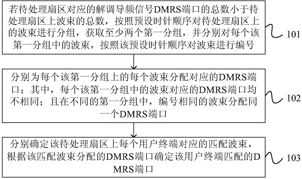
[0080] figure 1 A flow chart of the MIMO-based pilot allocation method provided in Embodiment 1 of the present invention, as shown in figure 1 As shown, the method in this embodiment includes the following steps.

[0081]Step 101. If the total number of demodulation pilot signal DMRS ports corresponding to the sector to be processed is less than...


PUM


Abstract

The invention provides an MIMO (multiple-input multiple-output) based pilot frequency distribution method and an MIMO based pilot frequency distribution device. The method comprises the steps of grouping wave beams on a sector to be processed according to a preset clockwise sequence if the total number of demodulation reference signal (DMRS) ports corresponding to the sector to be processed is less than the total number of the wave beams on the sector to be processed, acquiring at least two first groups, and numbering the wave beams according to the preset clockwise sequence for the wave beams in each first group; distributing a corresponding DMRS port to each wave beam in each first group; distributing the same DMRS port to wave beams with the same number in different first groups; and respectively determining a matching wave beam corresponding to each user terminal on the sector to be processed, and determining DMRS ports matched with the user terminals according to the DMRS ports distributed to the matching wave beams. The embodiment of the invention breaks restrictions imposed on the number of user layers by maximum matching in the prior art, thereby effectively improving the demodulation performance.

Description

technical field [0001] Embodiments of the present invention relate to communication technologies, and in particular to a MIMO-based pilot allocation method and device. Background technique [0002] At present, multiple-input multiple-output (MIMO for short) is generally divided into single-user multiple-input multiple-output (Single-User MIMO, SU-MIMO for short) and multi-user multiple-input multiple-output (Multi-User MIMO, MU-MIMO for short). There are two types of MIMO; among them, SU-MIMO refers to a point-to-point antenna link between a base station and a user. MU-MIMO means that several users use the same time domain and frequency domain resources to communicate with a base station at the same time. Since MU-MIMO can transmit multiple space-division multiplexed data streams to different users at the same time, the gain of MU-MIMO is particularly obvious as the number of base station transmit antennas increases. For example, the largest space-division multiplexing The...

Claims


Application Information

Patent Timeline
Patent Type & Authority Applications(China)
IPC IPC(8): H04L5/00H04B7/04
CPCH04B7/04H04L5/00
Inventor 杨晶
Owner HUAWEI TECH CO LTD
Learn More