Multimodal flight conversion control method for hybrid layout rotary-wing unmanned aerial vehicle

A mode conversion, unmanned rotor technology, applied in the direction of flight direction control, rotorcraft, aircraft control, etc., can solve the problem that the rotorcraft cannot fly at high speed, does not have vertical take-off and landing ability and hovering ability.

Inactive Publication Date: 2016-01-13
BEIHANG UNIV
View PDF5 Cites 17 Cited by
  • Summary
  • Abstract
  • Description
  • Claims
  • Application Information

AI Technical Summary

Problems solved by technology

[0003] However, the rotorcraft has the following problems: although the rotorcraft can realize jumping or ultra-short-distance take-off through pre-rotation, and achieve ultra-short-distance landing through the efficient deceleration of the rotor, the rotorcraft cannot fly at high speed like a fixed-wing aircraft. Capable of vertical take-off and landing and hovering
[0006] While expanding the flight envelope and enhancing mission adaptability, the hybrid layout rotor UAV also brings many technical problems: First, because the hybrid layout ro

Method used


Image

  • Multimodal flight conversion control method for hybrid layout rotary-wing unmanned aerial vehicle
  • Multimodal flight conversion control method for hybrid layout rotary-wing unmanned aerial vehicle
  • Multimodal flight conversion control method for hybrid layout rotary-wing unmanned aerial vehicle

Examples


Embodiment Construction

[0030] The present invention will be described in detail below in conjunction with the drawings and embodiments.

[0031] The present invention provides a multi-modal flight conversion control method for a hybrid layout rotary wing drone. The hybrid layout rotary wing drone adopts a tip jet drive / rotor / fixed wing hybrid layout. The hybrid layout Rotor UAV includes: fixed-wing aircraft body, drive / rotor rotor system, propulsion aero engine and flight control system, see patent reference [1]: application number 201410852017.X, invention name: a composite multi-mode The present invention is based on the compound multi-mode multi-purpose aircraft.

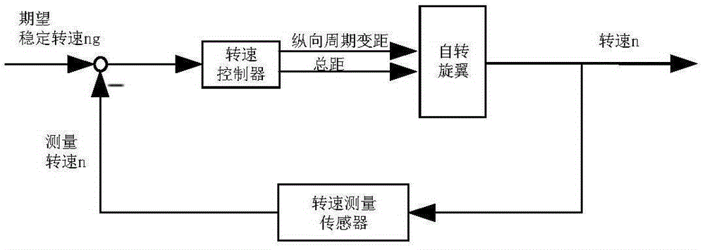
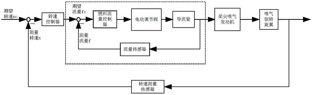
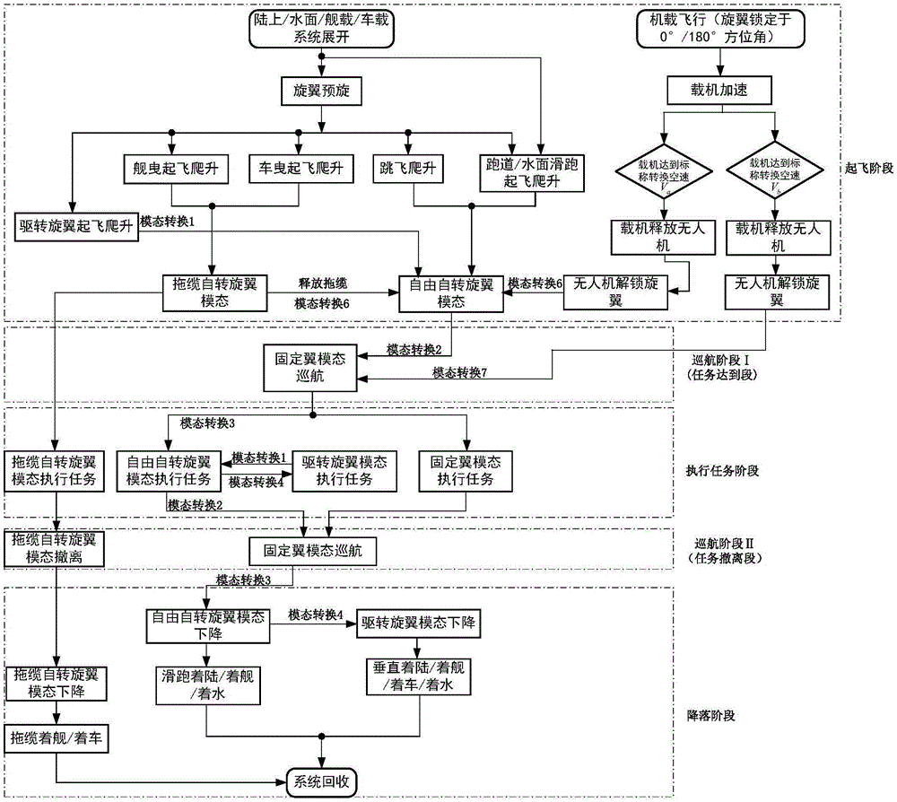
[0032] The hybrid layout rotor UAV adopts a composite layout based on tip jet driving / rotating rotor / fixed wing. According to the driving mode and speed range of the rotor, the following three flight modes can be realized: tip jet driving Rotor wing mode, autorotor wing mode and fixed wing mode. In addition, if the parent aircraft launch m...


PUM


Abstract

The invention discloses a multimodal flight conversion control method for a hybrid layout rotary-wing unmanned aerial vehicle, and relates to the technical field of flight control for unmanned aerial vehicles. Based on composite multimodal multipurpose aircrafts, the hybrid layout rotary-wing unmanned aerial vehicle comprises five types of flight modal; and aiming at a take-off/air-drop stage, a task arriving stage, a task executing stage, a task evacuating stage and a landing/recovery stage respectively, the multimodal flight conversion control method provides seven modal conversion modes and conversion opportunities. According to the multimodal flight conversion control method provided by the invention, the hybrid layout rotary-wing unmanned aerial vehicle can be reasonably converted among various modal types to meet different task requirements, and the multimodal flight capability and the multitask capability of the hybrid layout rotary-wing unmanned aerial vehicle can be sufficiently exerted; and the general land take-off and landing capability of the hybrid layout rotary-wing unmanned aerial vehicle can be sufficiently exerted, the flexible water-surface/carrier-borne/vehicle-mounted/airborne drop and other deployment modes of the hybrid layout rotary-wing unmanned aerial vehicle can be utilized, and the high-speed cruise capability and the low-altitude and low-speed capability of the hybrid layout rotary-wing unmanned aerial vehicle can be sufficiently exerted, so as to achieve the rapid arriving and evacuating as well as low-speed and low-altitude task executing capabilities of the hybrid layout rotary-wing unmanned aerial vehicle.

Description

Technical field [0001] The invention relates to a multi-mode conversion control method for a hybrid layout rotary wing drone, and relates to the technical field of drone flight control. Background technique [0002] Rotor-type aircraft can be divided into helicopters and autogyro (referred to as rotorcraft) according to whether the rotor is driving or not. The helicopter can realize vertical take-off and landing and low-altitude hovering, and has superior maneuverability, which can realize hovering, vertical flight, inverted flight and side flight. However, helicopters have complex structures, high vibration and noise, and low speed limits. Compared with helicopters, rotorcraft has simple structure, low air-to-weight ratio, low cost, and higher aerodynamic efficiency. Compared with fixed-wing aircraft, rotorcraft can take off and land in a short distance, and has good low-speed flight performance and is not easy to stall. In recent years, the unique advantages of rotorcraft and...

Claims


Application Information

Patent Timeline
IPC IPC(8): B64C9/00B64C15/00B64C27/22
Inventor 蔡志浩林清闫坤王英勋
Owner BEIHANG UNIV
Why Eureka
Try Eureka