
Elevator car accidental movement protection device, braking unit and control method for braking unit

A technology of accidental movement and protection device, applied in the field of elevators, which can solve problems such as malfunction, increased workload, and direct action of the braking unit, and achieve the effect of solving reset problems, improving safety and reliability, and preventing malfunction

Active Publication Date: 2018-11-02
ZOOMLION HEAVY IND CO LTD
View PDF7 Cites 0 Cited by
  • Summary
  • Abstract
  • Description
  • Claims
  • Application Information

AI Technical Summary

Problems solved by technology

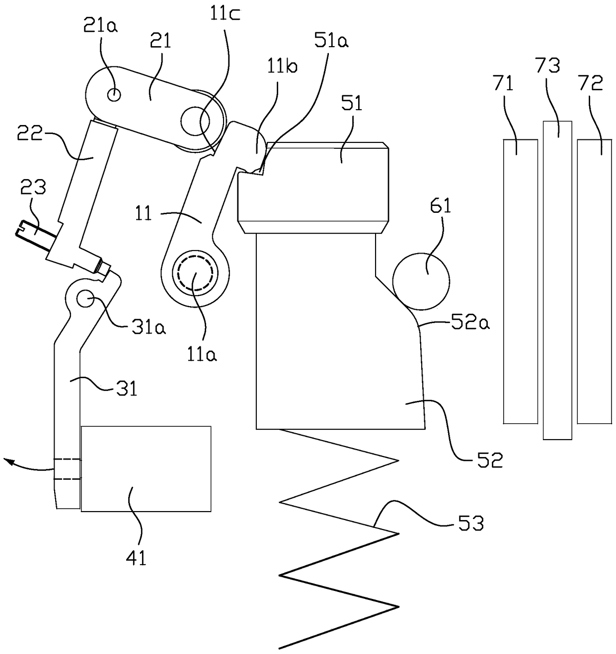
[0004] However, the brake unit of the prior art used for the elevator car accidental movement protection device is in a long-term standby state because the electromagnet 41 is energized for a long time, but the brake unit is powered by a backup power supply. When the power supply is insufficient, the electromagnetic force of the brake unit If the iron 41 loses power, it will cause the brake unit to act directly, and there is a risk of misoperation. After the brake unit malfunctions, it needs to be reset again, which increases additional workload; moreover, when the steel wire rope 73 is installed on site, the brake unit It is also necessary that the movable splint 71 is in the open state under the energized state, so that there is a safety risk when the steel wire rope 73 is installed.

Method used


Image

  • Elevator car accidental movement protection device, braking unit and control method for braking unit
  • Elevator car accidental movement protection device, braking unit and control method for braking unit
  • Elevator car accidental movement protection device, braking unit and control method for braking unit

Examples


Embodiment Construction

[0023] In order to further explain the technical means and effects of the present invention to achieve the intended purpose, the following will be combined with the accompanying drawings and preferred embodiments to describe the elevator car accidental movement protection device, braking unit and braking unit according to the present invention. The specific implementation, structure, features and effects of the control method are described in detail below.

[0024]The aforementioned and other technical contents, features and effects of the present invention will be clearly presented in the following detailed description of the preferred embodiments with reference to the drawings. Through the description of the specific implementation, the technical means and effects of the present invention to achieve the intended purpose can be understood more deeply and specifically, but the accompanying drawings are only for reference and description, and are not used to limit the present in...


PUM


Abstract

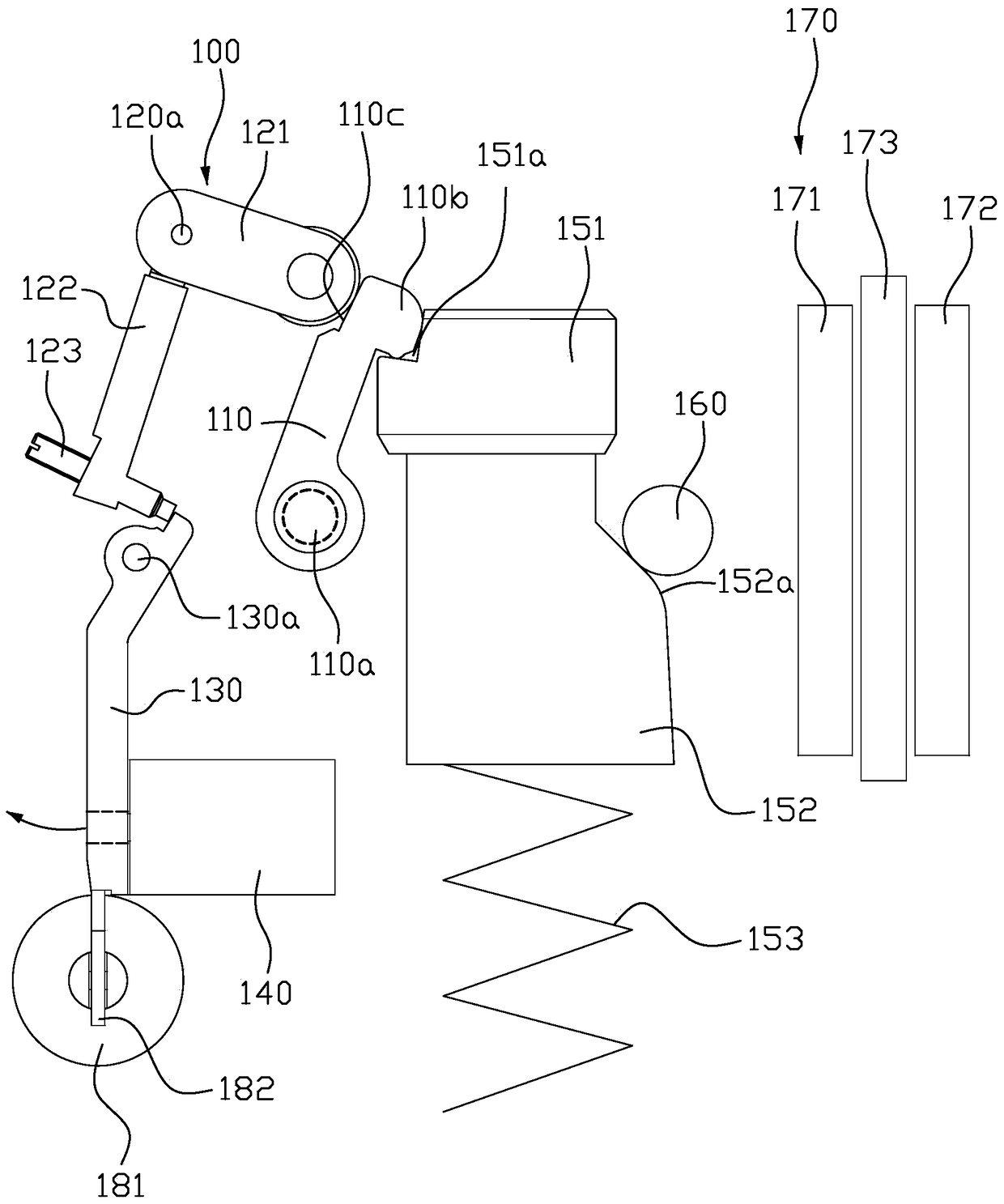
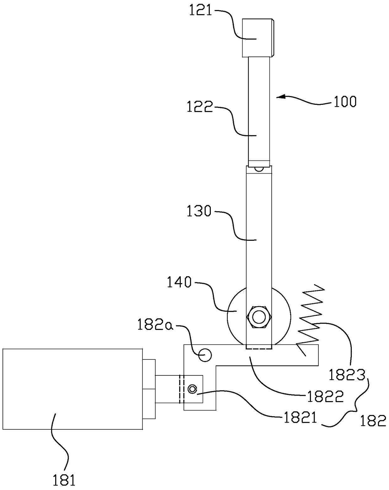
The invention provides a brake unit for an unintended car movement protection device. The brake unit comprises a drive structure and a brake structure. The brake structure comprises a movable clamping plate and a fixed clamping plate which are opposite to each other. A steel wire rope is arranged between the movable clamping plate and the fixed clamping plate. A drive structure comprises a first magnet and an electromagnet oscillating rod. The electromagnet oscillating rod is provided with an attraction position and an unlocking position. The electromagnet oscillating rod is attracted by the first magnet at the attraction position. The electromagnet oscillating rod is released through the first magnet at the unlocking position. The drive structure drives the movable clamping plate to be close to the fixed clamping plate so as to brake the steel wire rope. The brake unit further comprises a second electromagnet and a limiting structure. The limiting structure abuts against the electromagnet oscillating rod to prevent the electromagnet oscillating rod from moving towards the unlocking position. The second electromagnet is connected with the limiting structure and used for driving the limiting structure to be separated from the electromagnet oscillating rod. The brake unit can prevent the false operation caused by unexpected power outage effectively, and the safety and reliability of products are improved.

Description

technical field [0001] The invention relates to the technical field of elevators, in particular to an elevator car accidental movement protection device, a braking unit used in the elevator car accidental movement protection device and a control method for the braking unit. Background technique [0002] UCMP (Unintended car movement protection system), that is, the accidental movement protection of the car, mainly focuses on the improvement of the safety performance of the elevator. When the elevator is at the leveling position and the door is opened, if the elevator moves unexpectedly, the UCMP safety device will immediately activate the protection and stop the elevator Running, adding a safety guarantee for passengers. [0003] figure 1 It is the original schematic diagram of the structure of a brake unit used in the elevator car accidental movement protection device, please refer to figure 1 , The brake unit includes a lock hook 11, a pendulum bracket 21, a pendulum 22,...

Claims


Application Information

Patent Timeline
Patent Type & Authority Patents(China)
IPC IPC(8): B66B5/16
Inventor 王伟峰贾国涛姜鸣
Owner ZOOMLION HEAVY IND CO LTD
Learn More