Vertical shaft construction device and method

A construction device and shaft technology, which is applied in shaft equipment, earthwork drilling, shaft lining, etc., can solve the problem that the anti-heaving amount of the subway cannot meet the design requirements, and achieve the effect of strong structure and high safety

Active Publication Date: 2016-01-13
CHINA RAILWAY SHANGHAI ENGINEERING BUREAU GROUP CO LTD +1
View PDF14 Cites 8 Cited by
  • Summary
  • Abstract
  • Description
  • Claims
  • Application Information

AI Technical Summary

Problems solved by technology

[0004] The invention provides a shaft construction device and method, aiming to improve the problem that the anti-hea

Method used


Image

  • Vertical shaft construction device and method
  • Vertical shaft construction device and method

Examples


Embodiment 1

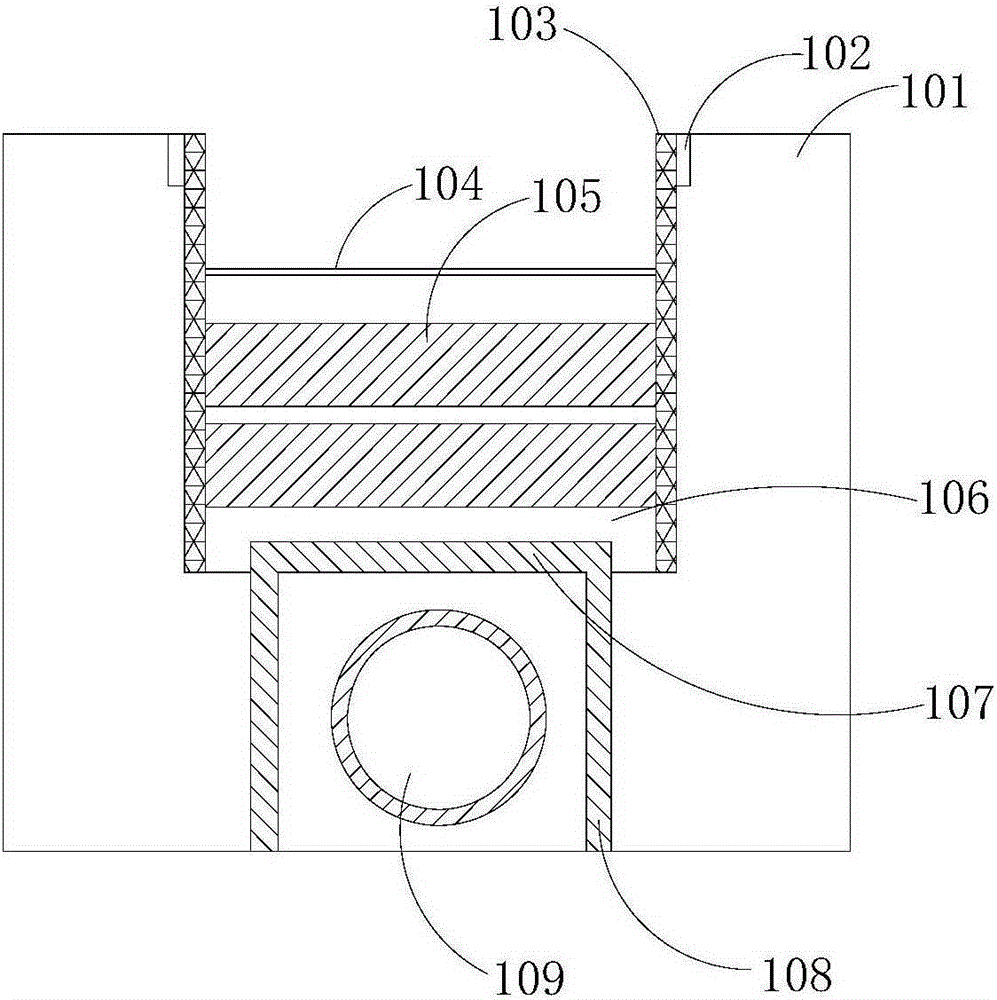
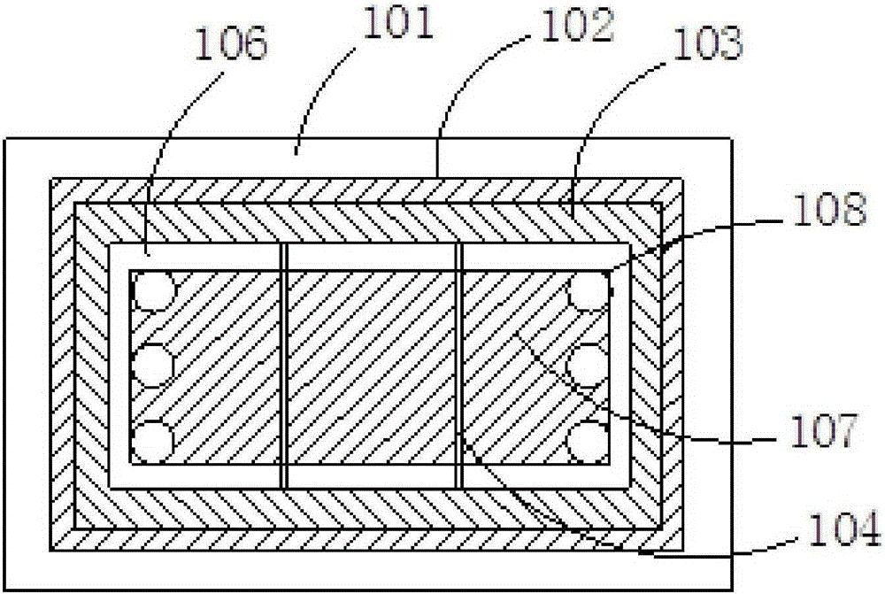
[0068] A shaft construction device, comprising a ring beam 102, a support 103, a support system and an anti-floating structure, the ring beam 102 is arranged in the soil 101 above the tunnel 109, the support 103 is a steel bar grid sprayed with concrete, and the support 103 is applied on the side wall of the shaft. The support system is a multi-layer structure, including a steel support structure 104 and a partition structure 105 arranged vertically. place. The height of the steel support structure 104 from the ground is 2.5m, and the middle partition structure 105 is fixedly connected in turn to form a middle partition wall, and the height of the top of the middle partition wall from the ground is 4.5m. The height between the bottom of the middle partition wall and the top of the anti-floating plate 107 is 1m. The support system is fixedly connected to the supports 103 on both sides of the shaft, and the anti-floating structure includes an anti-floating plate 107 and an anti...

Embodiment 2

[0070] A shaft construction device, comprising a ring beam 102, a support 103, a support system and an anti-floating structure, the ring beam 102 is arranged in the soil 101 above the tunnel 109, the support 103 is a steel bar grid sprayed with concrete, and the support 103 is applied on the side wall of the shaft. The support system is a multi-layer structure, including a steel support structure 104 and a partition structure 105 arranged vertically. place. The height of the steel support structure 104 from the ground is 3.5m, and the middle partition structure 105 is fixedly connected in turn to form a middle partition wall, and the height of the top of the middle partition wall from the ground is 5.5m. The height between the bottom of the middle partition wall and the top of the anti-floating plate 107 is 1.5m. The support system is fixedly connected to the supports 103 on both sides of the shaft, and the anti-floating structure includes an anti-floating plate 107 and an an...

Embodiment 3 1

[0071] Embodiment 3 A kind of shaft construction method, comprises the following steps:

[0072] a. Excavate and construct the ring beam 102 in the protection area above the tunnel, and then cure it to make the concrete strength reach 100%.

[0073] b. After the concrete to be poured meets the design strength, excavate from top to bottom in the ring beam 102 to protect the earth above the subway. The depth of each excavation is 0.5m. Support 103.

[0074] c. When the installation depth of the support reaches 3m, after setting two steel support structures 104 at the trisection point in the length direction of the shaft, repeat step b.

[0075] d. When the installation depth of the support reaches 5m, two intermediate partition structures 105 are arranged at the trisection point in the length direction of the shaft. The intermediate partition structures 105 are steel bar structures, including main reinforcement, and the main reinforcement is the intermediate partition structure...


PUM

PropertyMeasurementUnit
Heightaaaaaaaaaa

Abstract

The invention provides a vertical shaft construction device and a method, and belongs to the field of foundation engineering construction. The device comprises a ring beam, supports, a support system and floating prevention structures, wherein the ring beam is arranged in a soil body above a tunnel; the supports are applied to the side walls of a vertical shaft; the support system is a multilayer structure, and comprises a steel support structure and a middle separation plate structure arranged in the vertical direction; the support system is perpendicular to the length direction of the vertical shaft, and is fixedly connected with the supports at the two sides of the vertical shaft; and the floating prevention structures are positioned at the upper side and the left and right sides of the tunnel. The span of the vertical shaft is small, the device is provided with the multilayer support system, and the vertical shaft construction device is strong in structure, so that the pressure of soil bodies at the two sides of the tunnel can be preferably transferred, the interference on the soil bodies around the subway tunnel is little, and the swell quantity of the tunnel can be effectively controlled to satisfy the design requirement. In addition, the symmetric parallel operation can be adopted to synchronously construct and install the device on multiple working surfaces, so that the construction period is reduced.

Description

technical field [0001] The invention relates to the field of foundation engineering construction, in particular to a shaft construction device and method for preventing existing lines from uplifting. Background technique [0002] With the rapid development of my country's economy and the continuous construction of infrastructure facilities, there will be more and more subway lines in every developed city, and more and more dense. However, the construction of ground surface structures will definitely have an impact on the existing subway lines, especially when the construction of the deep foundation pit spans the existing lines, it will have a particularly large impact on the existing lines. However, in the various existing construction methods, there are many disadvantages, such as construction speed, economic cost, and influence range need to be greatly improved. [0003] For the construction of subway protection, the current main plan is to carry out grouting and reinforc...

Claims


Application Information

Patent Timeline
IPC IPC(8): E21D7/00E21D5/04
Inventor 周庙林吕小军邵凯强徐玉成李海滨黄潇豪王海波贾洪波江雷刘琳
Owner CHINA RAILWAY SHANGHAI ENGINEERING BUREAU GROUP CO LTD
Why Eureka
Try Eureka