Refrigerator box frame and refrigerator
A technology for box frames and refrigerators, which is applied to household refrigeration devices, lighting and heating equipment, household appliances, etc. It can solve the problems of increased cost and production difficulty, easy shrinkage of product appearance surface, and impact on appearance quality, and achieves small mold structure changes , easy to realize and popularize the application, and improve the effect of strength
- Summary
- Abstract
- Description
- Claims
- Application Information
AI Technical Summary
Problems solved by technology
Method used
Image
Examples
Embodiment 1
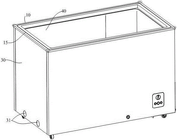
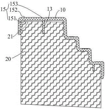
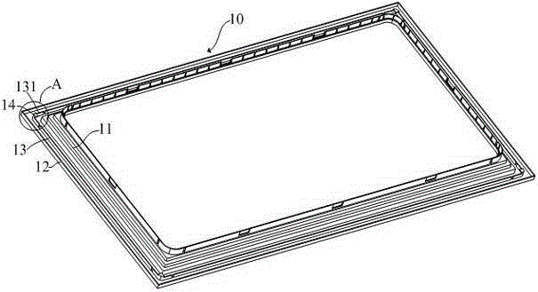
[0018] refer to image 3 , Figure 4 and Figure 6 , the present embodiment is a freezer box frame, same as the prior art, the box frame 10 is fixed on the upper end surface 21 of the foam layer 20 of the freezer, and is used to seal and cooperate with the door seal of the freezer body to ensure the sealing of the freezer. The box frame 10 includes a top wall 15 positioned above the upper end face 21 of the foam layer, an inner side wall 11 positioned inside the upper end face 21 of the foam layer, and an outer side wall 12 positioned outside the upper end face 21 of the foam layer, that is, its vertical section is inverted. U-shaped; the lower surface 151 of the top wall 15 (that is, the surface opposite to the upper end surface 21 of the foam layer) is provided with an annular reinforcing rib 13. Unlike the prior art, the four corners of the box frame 10 in the present embodiment The annular reinforcing rib 13 is provided with a hook 14, the hook 14 includes a connecting p...
Embodiment 2
[0029] refer to Figure 7 , different from Embodiment 1, in this embodiment, the hook 14 is not located on the corner 1311 of the corner rib 131, but on its side, specifically on one of the side 1312, as shown in Figure 7 As shown, the hook 14 is specifically formed on the inner side of the section of the rib. Since some types of freezers need to be equipped with dew removal pipe 40, the dew removal pipe 40 should be closely attached to the inner surface of the ring rib 13 when assembling, refer to Figure 8 In order not to affect the assembly of the dew removal pipe 40, the cross-sectional area of the root of the hook 14 should be smaller than that of the hook, that is, the root size should be as small as possible. Of course, in this embodiment, the hook 14 can also be located at other positions of the ribs in this section, but it is also based on the convenience of assembling the box frame 10 and the dew pipe 40 .
Embodiment 3
[0031] The difference from the above two embodiments is that in this embodiment, hooks 14 are provided between the four corners of the box frame 10 and the inner wall 11 between the annular ribs 13, specifically, the hooks 14 are located at the corners of the ribs in this embodiment. 131 and the inner wall 11. Also for a refrigerator that needs to be equipped with a dew removal pipe, the specific position of the hook 14 is subject to the convenience of assembling the dew removal pipe.
PUM
 Abstract
Description
Claims
Application Information
 - R&D
- Intellectual Property
- Life Sciences
- Materials
- Tech Scout
- Unparalleled Data Quality
- Higher Quality Content
- 60% Fewer Hallucinations
Browse by: Latest US Patents, China's latest patents, Technical Efficacy Thesaurus, Application Domain, Technology Topic, Popular Technical Reports.
© 2025 PatSnap. All rights reserved.Legal|Privacy policy|Modern Slavery Act Transparency Statement|Sitemap|About US| Contact US: help@patsnap.com


