
A connection structure between corner frame and railing frame

A connection structure and outer frame technology, applied in the field of doors and windows, can solve the problems of high manufacturing cost of the corner part, complex corner frame structure, and difficult installation of doors and windows, etc., and can easily guarantee the waterproof treatment effect, improve the waterproof treatment effect, and save the installation process Effect

Active Publication Date: 2021-12-07
欣叶安康科技股份有限公司
View PDF6 Cites 0 Cited by
  • Summary
  • Abstract
  • Description
  • Claims
  • Application Information

AI Technical Summary

Problems solved by technology

[0002] Traditional doors and windows are separated from the exterior design of the building. Doors and windows are just a separate product of themselves. The construction party needs to redesign the facade of the building, and it is independent of the design of doors and windows as a building. There are certain difficulties in the installation and construction of doors and windows, and it may even cause difficulties in the installation of doors and windows or in the construction of building facade decoration. Secondly, the construction of building facades is often completed outside the building, and the construction safety factor is low. Based on the above-mentioned problems, a one-piece window combining doors, windows and building facades has emerged as the times require, but the existing one-piece window has the following defects
[0003] (1) The existing corner frame is complex in structure, difficult to process, difficult to transport, and labor-intensive to carry during installation, resulting in too high manufacturing cost of the corner part. Disadvantages such as poor sealing performance;
[0004] (2) The structure of the decorative window sill outside the building is split, which requires secondary assembly and installation, which is time-consuming and laborious. At the same time, there will be serious water seepage problems in the building due to unreasonable installation;
[0005] (3) The outer frame is generally equipped with a drainage notch, but the existing drainage notch has poor drainage effect. When the wind and rain are too heavy, the rainwater is easily blown back by the strong wind, causing the backflow phenomenon to affect the drainage, and in severe cases, it seeps into the building;
[0006] (4) For different decoration styles, the chamfers cannot be replaced, and different types of corner frames need to be produced, resulting in waste of materials

Method used


Image

  • A connection structure between corner frame and railing frame
  • A connection structure between corner frame and railing frame
  • A connection structure between corner frame and railing frame

Examples


Embodiment 1

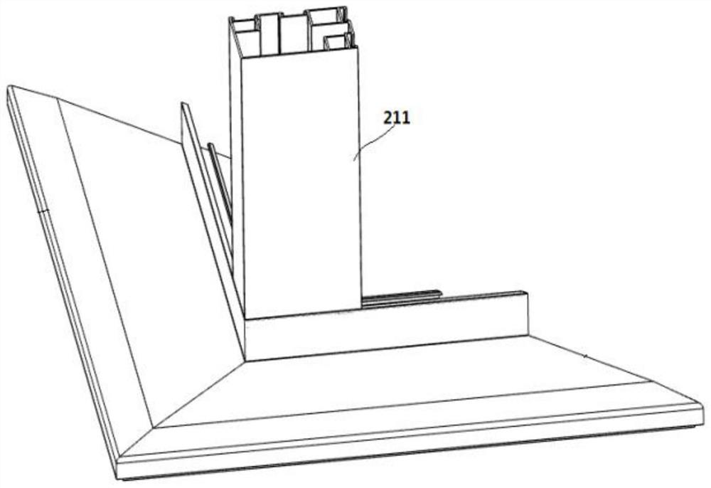
[0047] see Figure 1-8 , an embodiment provided by the present invention: a connection structure between a corner frame 211 and a railing frame, including a corner frame 211 and a corner frame assembly at a 90° corner, wherein the corner frame 211 is connected to the corner by a vertical corner code The outer frame components are fixedly connected;

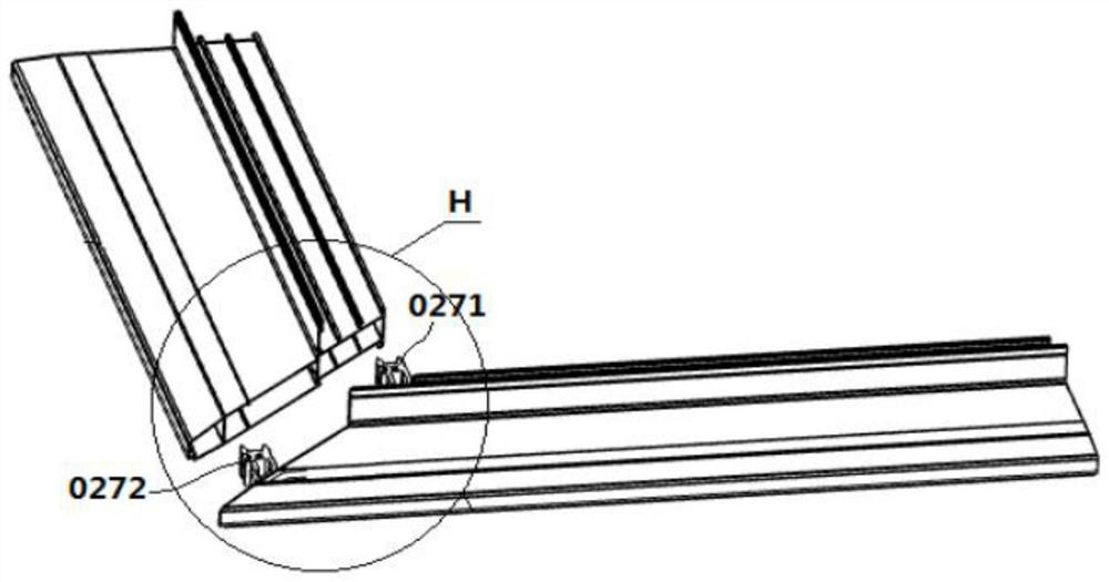
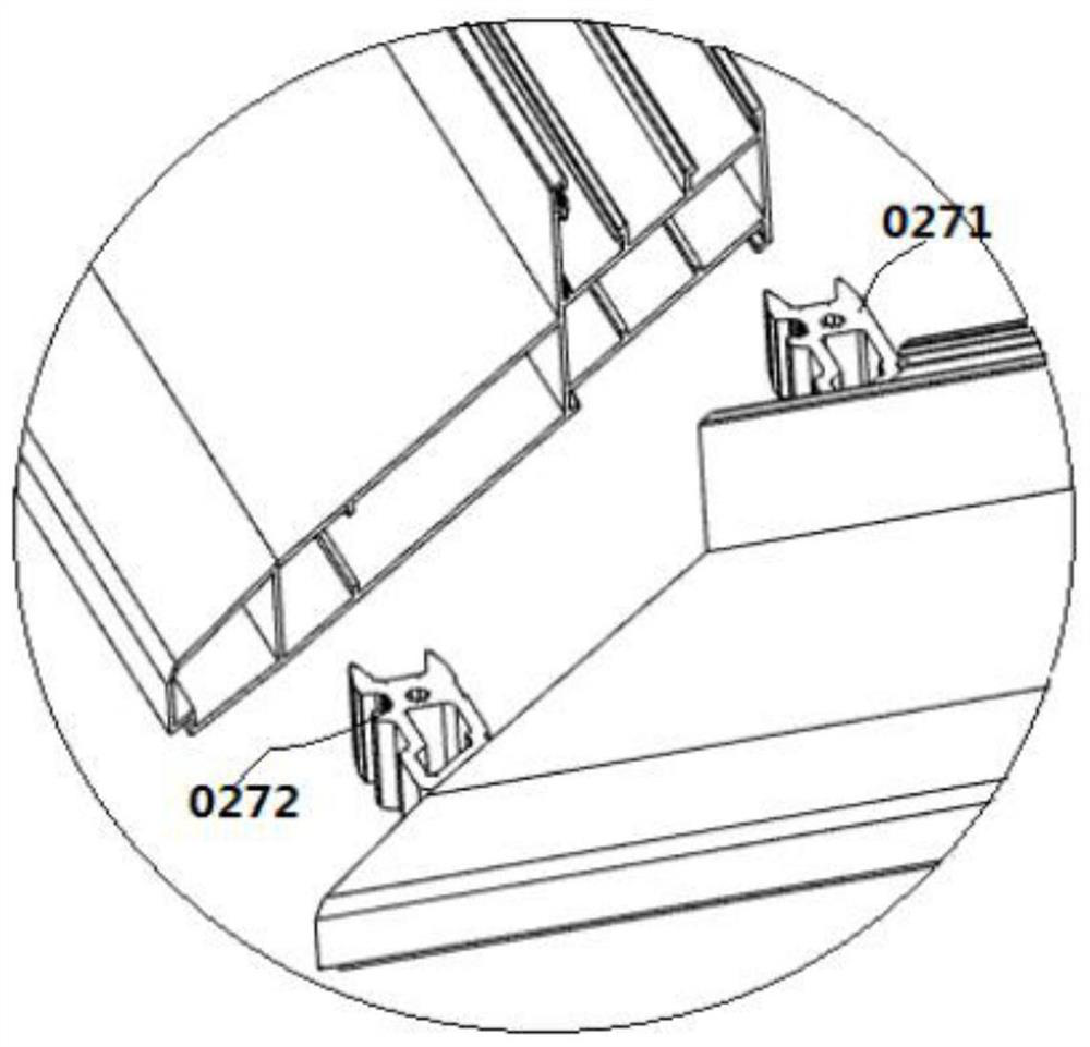
[0048] For details, please refer to Figure 1-3 , the corner outer frame assembly includes a railing outer frame with a cut angle of 45° connected on the same plane through the first transverse corner code 0271 and the second transverse corner code 0272. Through the above structure, the present invention cuts the two railing outer frames when the group is assembled. 45°normal group angle, the processing precision of this corner cutting process is high, and then the waterproof treatment here can be realized through appropriate glue, and the waterproof treatment effect is easy to guarantee. When connecting, glue can be injected in...

Embodiment 2

[0052] The difference between the second embodiment and the first embodiment is that

[0053] For details, please refer to Figure 9 , 10 , 11, 12 and 13, the outer corner of the corner frame 211 is slid to be provided with reinforcing assembly along its length direction, and the reinforcing assembly is the hollow bar-shaped body 1 that section is right-angle fan-shaped, and wherein, the arc surface of hollow bar-shaped body 1 and right angle An outwardly protruding limit bar 11 is provided at the surface joint, and the corner frame 211 on one side of the limit bar 11 is provided with a limit groove 12 that matches the limit bar 11, and two limit baffles are provided at the corner positions There is a corner connection assembly, and the corner connection assembly includes a top plate 3 that fits with the upper end faces of the two limit baffles at the corner positions, and is vertically arranged at the bottom of the top plate 3 and fits with the third limit rib 2616 of the tw...

Embodiment 3

[0056] see Figure 14-19 , an embodiment provided by the present invention: a connection structure between a corner frame 211 and a railing frame, including a corner frame 211 and a corner frame assembly at a 90° corner, wherein the corner frame 211 is connected to the corner by a vertical corner code The outer frame components are fixedly connected;

[0057] For details, please refer to Figure 1-3 , the corner outer frame assembly includes a railing outer frame with a cut angle of 45° connected on the same plane through the first transverse corner code 0271 and the second transverse corner code 0272. Through the above structure, the present invention cuts the two railing outer frames when the group is assembled. 45°normal group angle, the processing precision of this corner cutting process is high, and then the waterproof treatment here can be realized through appropriate glue, and the waterproof treatment effect is easy to guarantee. When connecting, glue can be injected ...


PUM


Abstract

The invention discloses a connection structure between a corner frame and a railing outer frame, comprising a corner frame and a corner outer frame assembly with a 90° corner, wherein the corner frame is fixedly connected to the corner outer frame assembly through a vertical corner code; the corner The outer frame assembly includes a railing outer frame with a cut angle of 45° connected on the same plane through the first horizontal corner code and the second horizontal corner code. The corner frame of the present invention is simple in structure, and it can be used in conjunction with L-shaped strip plates to form square tubes when the corners are used. It can be applied to other parts of doors and windows, and has strong practicability. Changing between angles and right angles to adapt to different architectural styles, for manufacturers, it not only reduces production costs, reduces the use of materials, avoids waste, saves resources, but also reduces the energy consumption of the production line and the emission of pollutants. emissions, in response to the national energy conservation and environmental protection policy.

Description

technical field [0001] The invention relates to the technical field of doors and windows, in particular to a connection structure between a corner frame and a railing outer frame. Background technique [0002] Traditional doors and windows are separated from the exterior design of the building. Doors and windows are just a separate product of themselves. The construction party needs to redesign the facade of the building, and it is independent of the design of doors and windows as a building. There are certain difficulties in the installation and construction of doors and windows, and it may even cause difficulties in the installation of doors and windows or in the construction of building facade decoration. Secondly, the construction of building facades is often completed outside the building, and the construction safety factor is low. Based on the above-mentioned problems, an integrated window that combines doors, windows and building facades has emerged as the times requi...

Claims


Application Information

Patent Timeline
Patent Type & Authority Patents(China)
IPC IPC(8): E06B3/964E06B3/96E06B7/14E06B1/70
CPCE06B1/702E06B3/9616E06B3/964E06B7/14
Inventor 谭潇军叶长清余国权程德进
Owner 欣叶安康科技股份有限公司
Learn More