
Display panel

a technology of display panel and panel body, applied in non-linear optics, instruments, optics, etc., can solve the problems of poor adhesion between the planarization layer and the metal layer or the insulation layer, affecting the strength of the panel, and affecting the reliability of the panel, so as to achieve the effect of improving strength

Active Publication Date: 2014-12-30
AU OPTRONICS CORP
View PDF7 Cites 0 Cited by
  • Summary
  • Abstract
  • Description
  • Claims
  • Application Information

AI Technical Summary

Benefits of technology

[0007]The invention is directed to a display panel having improved strength.
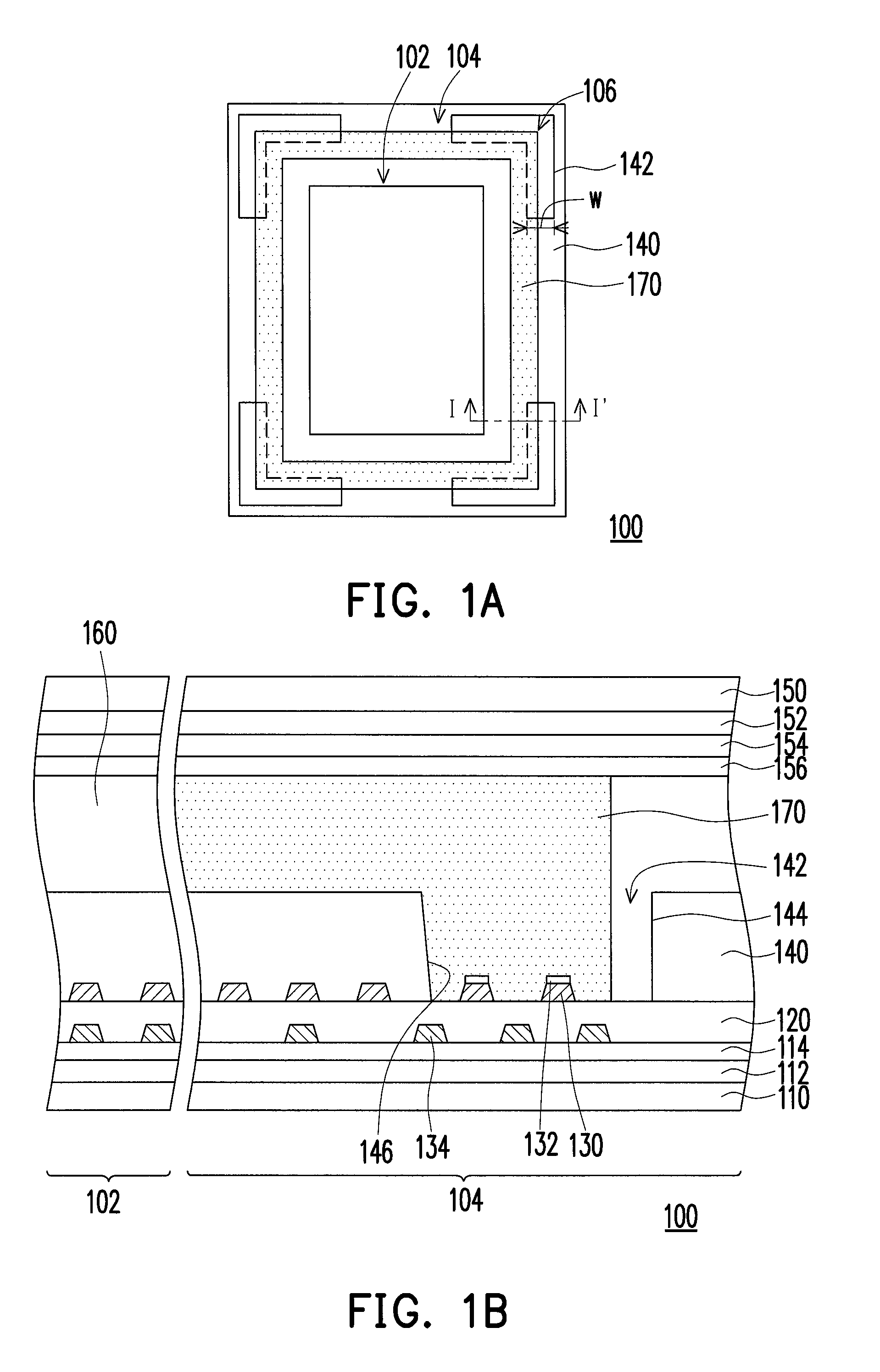
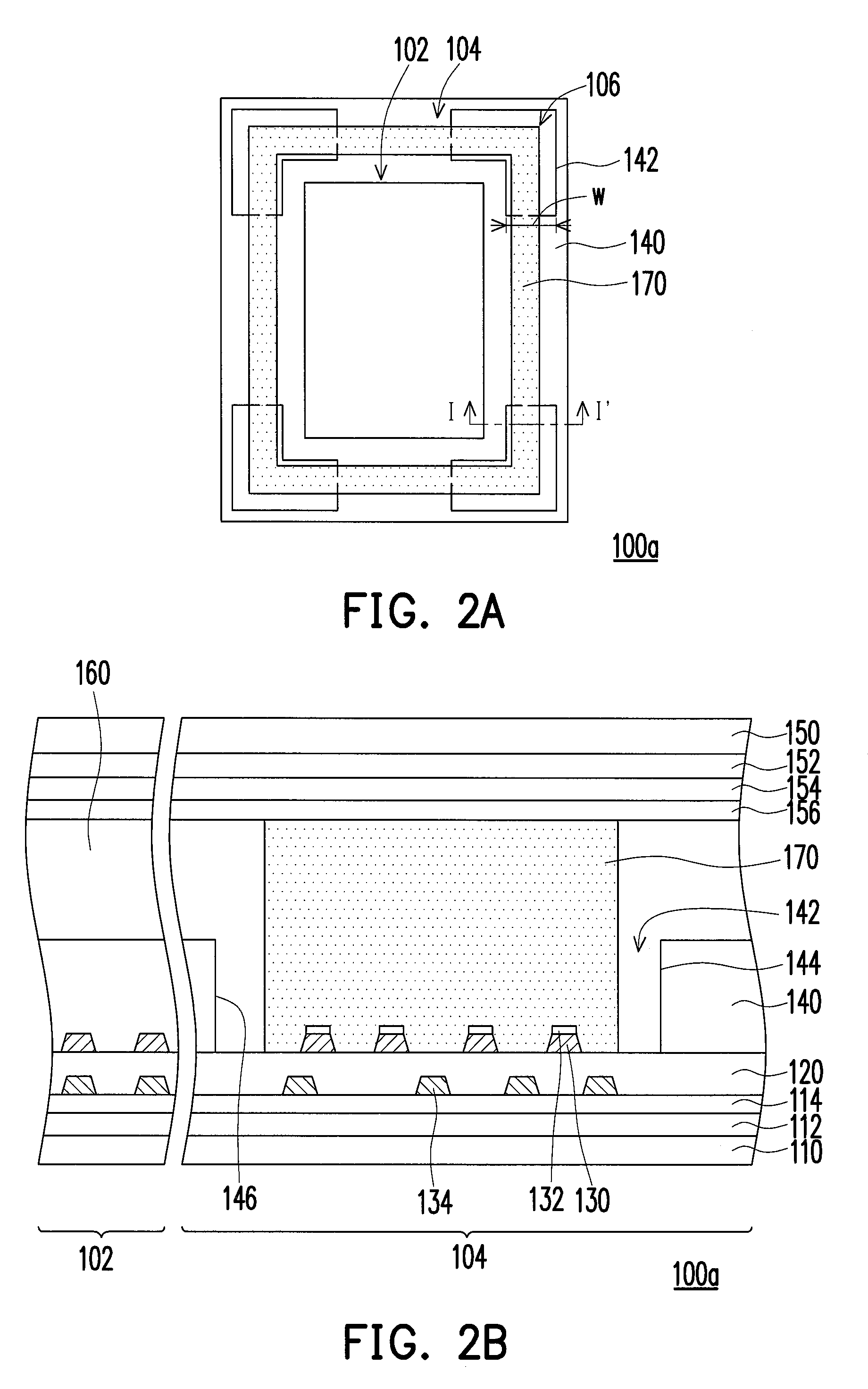
[0010]In light of the foregoing, in the display panel of the invention, the planarization layer has the opening exposing the corner of the sealant region. The sealant is filled in a part of the opening without covering at least a sidewall of the opening of the planarization layer. Consequently, the sealant contacts the dielectric layer directly through the opening to replace a weaker adhesion between the planarization layer and the dielectric layer with a stronger adhesion between the sealant and the dielectric layer so as to improve the strength of the corner of the panel significantly. Accordingly, the display panel of the invention has improved strength.

Problems solved by technology

However, the adhesion between the planarization layer and a metal layer or an insulation layer is poor.
When performing a strength test to the panel, the planarization layer usually peels off from the metal layer or the insulation layer easily, thereby affecting the strength of the panel.
Nevertheless, a peripheral circuit is usually disposed at a position corresponding to the sealant in panels with small dimension, and the removal of the planarization layer may cause damages such as oxidation and corrosion, thereby affecting the reliability of the panel.

Method used


Image

  • Display panel
  • Display panel
  • Display panel

Examples


Embodiment Construction

[0022]FIG. 1A is a schematic top view illustrating a display panel according to one embodiment of the invention. FIG. 1B is a schematic cross-sectional diagram taken along line I-I′ in FIG. 1A. For clarity of illustration, FIG. 1A merely shows a first substrate, a planarization layer, and a sealant. Referring to FIGS. 1A and 1B simultaneously, a display panel 100 includes a display region 102 and a sealant region 104. The sealant region 104 surrounds the display region 102, for example. The display panel 100 includes a first substrate 110, a dielectric layer 120, a first patterned conductive layer 130, a planarization layer 140, a second substrate 150, a display medium 160, and a sealant 170.

[0023]The dielectric layer 120 is disposed on the first substrate 110. The first patterned conductive layer 130 is at least partially disposed on the dielectric layer 120 in the sealant region 104. In the present embodiment, the first substrate 110 is, for instance, a glass substrate. The dielec...


PUM

PropertyMeasurementUnit
widthaaaaaaaaaa
size w1aaaaaaaaaa
size w2aaaaaaaaaa

Abstract

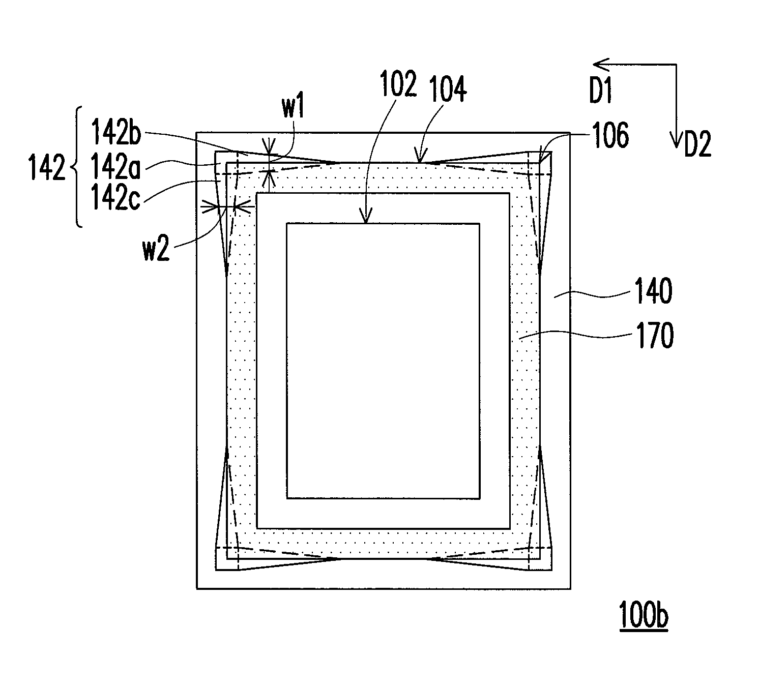
A display panel including a display region and a sealant region is provided. The display panel includes a first and a second substrate opposite to each other, a dielectric layer, a planarization layer, a display medium and a sealant. The dielectric layer is disposed on the first substrate. The planarization layer is disposed on the dielectric layer, and has at least one opening exposing the dielectric layer. The opening is disposed at a corner of the sealant region, where a width of the opening is gradually reduced as away from the corner. The display medium and the sealant are respectively disposed in the display and the sealant region between the first and the second substrate. The sealant is filled in a part of the opening without covering at least a sidewall of the opening of the planarization layer, and contacts the dielectric layer through the opening.

Description

CROSS-REFERENCE TO RELATED APPLICATION[0001]This application claims the priority benefit of Taiwan application serial no. 100142250, filed on Nov. 18, 2011. The entirety of the above-mentioned patent application is hereby incorporated by reference herein and made a part of this specification.BACKGROUND OF THE INVENTION[0002]1. Field of the Invention[0003]The invention relates to a display panel, more particularly to a display panel with improved strength.[0004]2. Description of Related Art[0005]In display panels, a planarization layer is usually adopted to reduce the coupling effect generated between the metal circuits in different layers so as to increase the aperture ratio. Accordingly, the space between the metal circuits in different layers can be reduced, so that the metal circuits in different layers can be overlapped. Generally, the planarization layer covers the entire substrate except contact holes and bonding pads. Thus, a sealant used for adhering two substrates is substa...

Claims


Application Information

Patent Timeline
Patent Type & Authority Patents(United States)
IPC IPC(8): G02F1/1339G02F1/1341
CPCG02F1/1341
Inventor CHIEN, WEI-YI
Owner AU OPTRONICS CORP
Learn More