Ripple current generation method and circuit
A ripple current and generation method technology, applied in the direction of regulating electrical variables, control/regulating systems, instruments, etc., can solve the problems of inconvenient use, large space, complicated wiring, etc., and achieve simple wiring, low cost, and versatility. strong effect
- Summary
- Abstract
- Description
- Claims
- Application Information
AI Technical Summary
Problems solved by technology
Method used
Image

Examples
no. 1 example
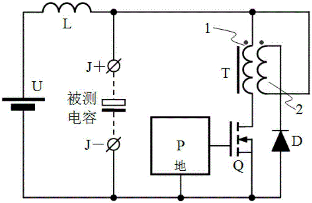
[0055] see figure 2 , a method for generating ripple current, which adopts method 1 in the technical solution, so I won’t go into details here, but explain here that the field effect tube is connected in series with the first winding of the transformer: the field effect tube is connected in series with the winding, according to the industry tradition, the field The effect tube is used as a controllable switch. Its gate is a control terminal and does not participate in series connection. Its drain and source participate in series connection.
[0056] A ripple current generation circuit, comprising a DC power supply U, an inductor L, a transformer T, a diode D, a field effect transistor Q, which is an N-channel type MOS transistor, a pulse width modulation control circuit P, and connected by The output terminals of the two pins for measuring capacitance include a positive terminal J+ and a negative terminal J-, the transformer T includes a first winding 1 and a second winding 2...
no. 2 example
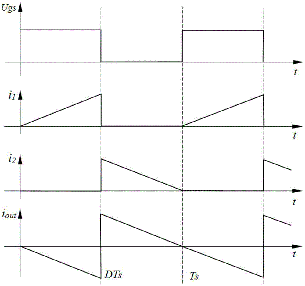
[0097] see image 3 , a method for generating ripple current, which adopts method two in the technical solution, and will not be repeated here. A ripple current generating circuit includes a DC power supply U, a capacitor C, an inductor L, a transformer T, and a diode D, a field effect transistor Q, is an N-channel MOS transistor, a pulse width modulation control circuit P, and an output terminal connected to two pins of the measured capacitor, including a positive terminal J+ and a negative terminal J-, the transformer T includes the first winding 1 and the second winding 2, the first winding 1 and the second winding 2 are bifilar windings, and the transformer T has a magnetic core with an air gap, and the output of the DC power supply U has a positive pole and the negative pole, the connection relationship is:
[0098] The positive terminal J+ of the output terminal of the measured capacitor is connected to one end of the inductor, the negative terminal J- of the output ter...
PUM
 Abstract
Description
Claims
Application Information
 - R&D Engineer
- R&D Manager
- IP Professional
- Industry Leading Data Capabilities
- Powerful AI technology
- Patent DNA Extraction
Browse by: Latest US Patents, China's latest patents, Technical Efficacy Thesaurus, Application Domain, Technology Topic.
© 2024 PatSnap. All rights reserved.Legal|Privacy policy|Modern Slavery Act Transparency Statement|Sitemap