Spectral microscopy device
A technique of microscopy and spectroscopy, applied in microscopes, measuring devices, Raman/scattering spectroscopy, etc.
- Summary
- Abstract
- Description
- Claims
- Application Information
AI Technical Summary
Problems solved by technology
Method used
Image

Examples
no. 1 example
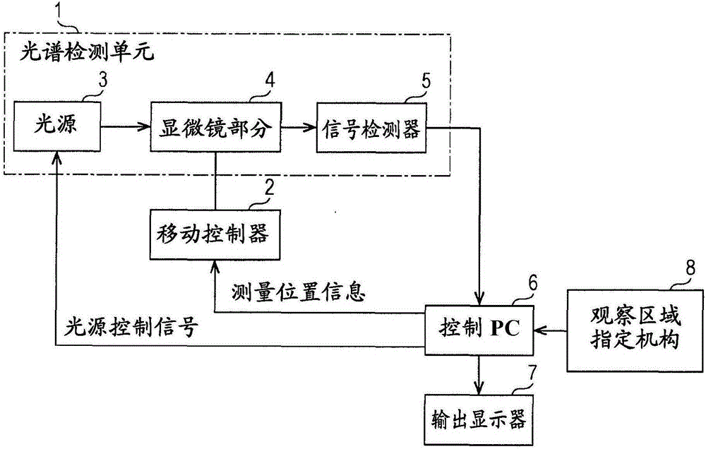
[0034] refer to figure 1 , as a first embodiment, an exemplary structure of a spectroscopic microscope apparatus to which the present invention is applied is described.
[0035] Such as figure 1 As shown, the spectral microscope apparatus according to the embodiment includes a spectral detection unit 1 , a movement controller (movement unit) 2 , a control PC 6 , an output display 7 , and an observation region specifying mechanism 8 . The spectrum detection unit 1 includes a light source 3 , a microscope section 4 and a signal detector 5 .
[0036] The light source 3 is a laser light source or other light sources. For example, among these light sources, a light source configured to be able to change or select a wavelength (a light source capable of controlling an output wavelength) is included.
[0037] The type of light source is not limited, so that the light source can be selected from light sources having wavelengths ranging from the millimeter wave region to the X-ray r...
no. 2 example
[0076] refer to Figure 4A with Figure 4B , as a second embodiment, an exemplary structure of an excitation Raman spectroscopy microscope device to which the present invention is applied is described. Figure 4A is a schematic diagram of the function according to the second embodiment of the present invention. Figure 4B is a schematic diagram showing the microscope part in more detail.
[0077] The spectroscopic microscope device according to the present invention can be formed not only as the excitation Raman spectroscopic microscope device described above, but also as a coherent anti-Stokes Raman scattering spectroscopic microscope device easily, if the optical filter becomes an optical filter words. Furthermore, spectroscopic microscopy devices according to the present invention can be formed into various other types of microscopy devices, such as multiphoton absorption spectroscopic microscopy devices and sum frequency generation spectroscopic microscopy devices, if a...
no. 3 example
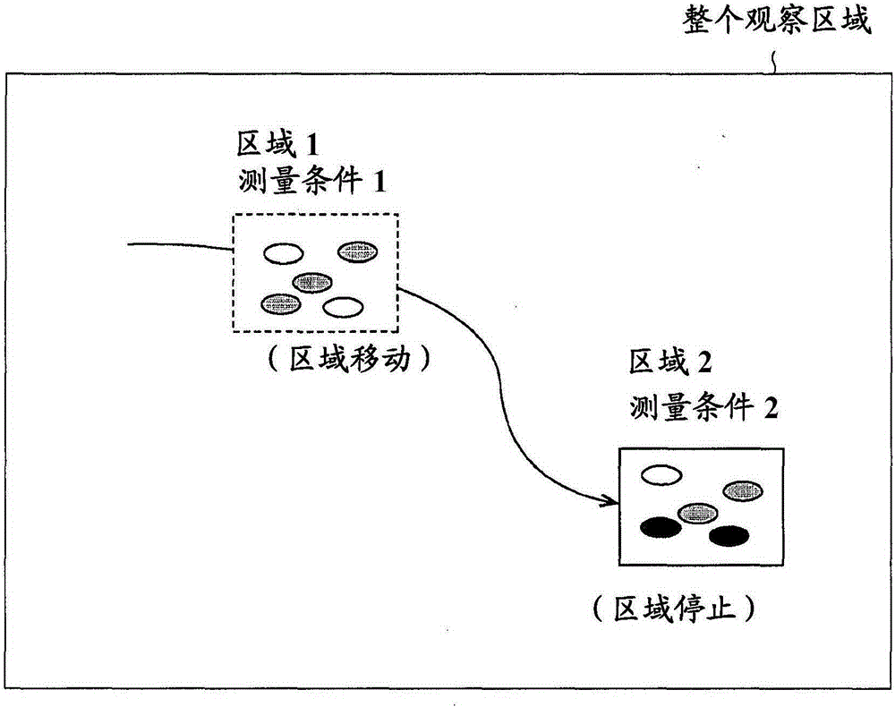
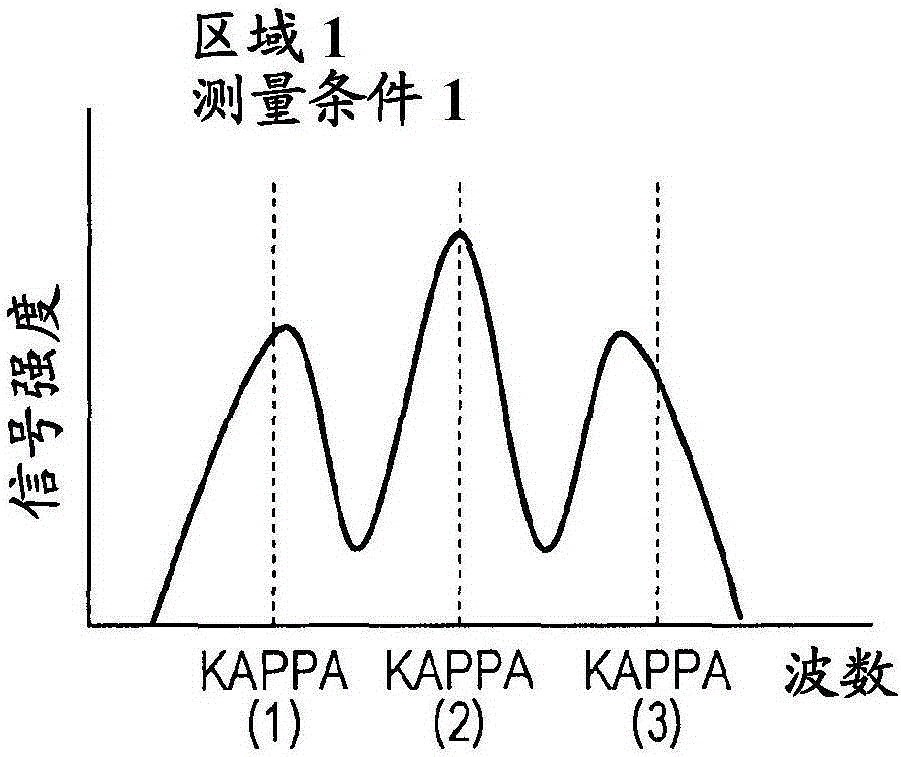
[0100] As a third embodiment, an exemplary structure using multivariate analysis for spectral analysis is described.
[0101] For example, multivariate analysis such as principal component analysis, independent component analysis, multiple regression analysis, or discriminant analysis can be performed to analyze spectral data including multidimensional components obtained in Examples.
[0102] If multivariate analysis is performed, it is possible to separate and extract signal sources even for complex multispectral originating from multiple sources.
[0103] Principal component analysis is a technique used to obtain new classification metrics from multivariate data. Independent component analysis is a technique for recovering independent signal sources using only the observed signals by allowing signal-independent transformations. Multiple regression analysis is a technique for obtaining the relationship between spectral components and signal sources and determining the signa...
PUM
 Abstract
Description
Claims
Application Information
 - R&D Engineer
- R&D Manager
- IP Professional
- Industry Leading Data Capabilities
- Powerful AI technology
- Patent DNA Extraction
Browse by: Latest US Patents, China's latest patents, Technical Efficacy Thesaurus, Application Domain, Technology Topic.
© 2024 PatSnap. All rights reserved.Legal|Privacy policy|Modern Slavery Act Transparency Statement|Sitemap