Trimming machine for end faces of pins

A dressing machine and pin technology, which is applied in the direction of machine tools suitable for grinding workpiece planes, parts of grinding machine tools, and grinding feed movement, etc. It can solve the problem of reducing production efficiency and not removing the protruding end of the stop pin Partial, time-consuming and labor-intensive problems, to achieve the effect of improving work efficiency

Active Publication Date: 2016-01-20
SHANGHAI HONGFENG IND
View PDF6 Cites 1 Cited by
  • Summary
  • Abstract
  • Description
  • Claims
  • Application Information

AI Technical Summary

Problems solved by technology

The current method of removing such protruding parts is to remove them one by one by hand with a spatula, but this method of removal is time-consuming and laborious, reducing production efficiency
[0003] And also there is not a kind of device that can remove the protruding part of stop pin end quickly at present

Method used


Image

  • Trimming machine for end faces of pins
  • Trimming machine for end faces of pins

Examples


Embodiment Construction

[0028] In order to make the technical means, creative features, objectives and effects achieved by the present invention easy to understand, the present invention will be further elaborated below.

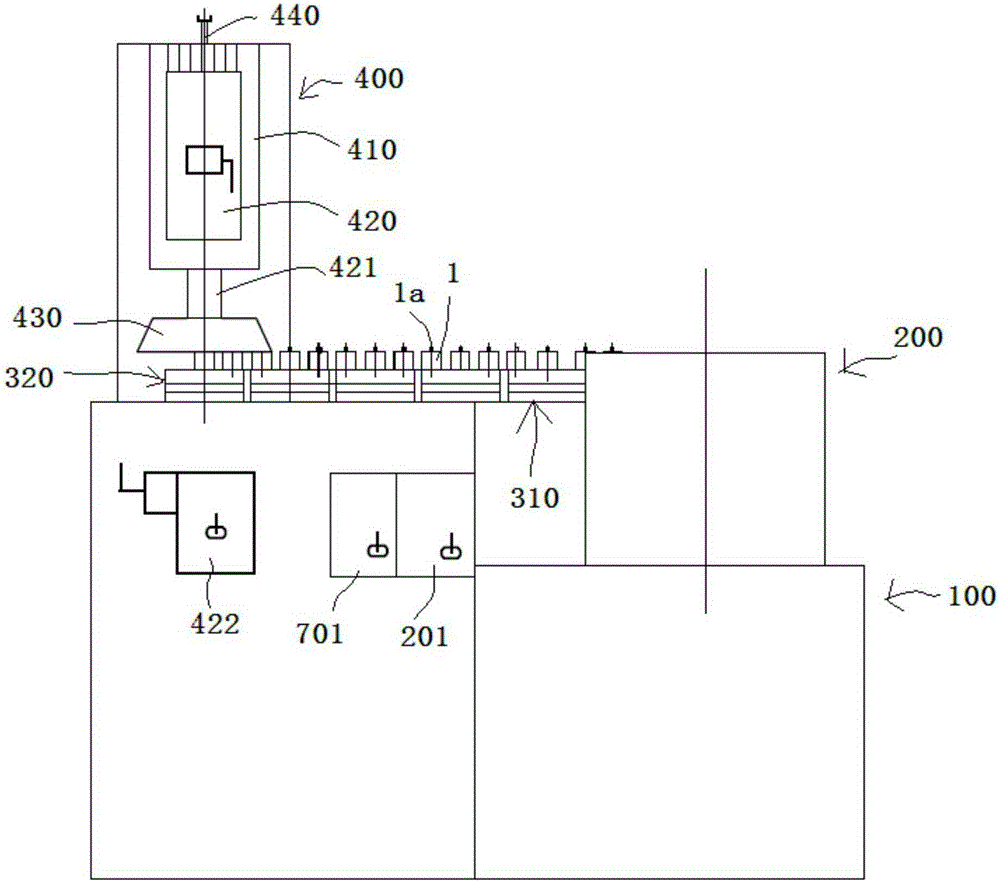
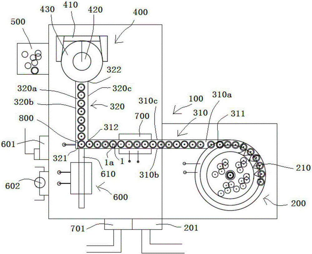
[0029] see figure 1 with figure 2 A pin end surface finishing machine shown includes a machine platform 100, which is provided with a graphite pin feeding device 200, a first feeding guide groove 310, a second feeding guide groove 320, a grinding device 400, and a receiving tray 500 , Linear pushing device 600.

[0030] The graphite pin feeding device 200 is a spiral magnetic feeder in the prior art, and the graphite pin feeding device 200 has a sorting device 210, so that the graphite pin 1 delivered by the discharge end of the graphite pin feeding device 200 is in a standing state, so that The protruding part 1a of the end surface of the graphite pin 1 faces upwards, which is convenient for grinding. The adjustment control switch 201 of the graphite pin feeding device 200 is ...


PUM


Abstract

The invention discloses a trimming machine for the end faces of pins. The trimming machine comprises a machine table, a graphite pin feeding device arranged on the machine table, a first feeding guide trough, a second feeding guide trough, a polishing device, a receiving disc and a linear pushing device. The first feeding guide trough and the second feeding guide trough are arranged on the machine table. The first end of the second feeding guide trough is in butt joint with the second end of the first feeding guide trough. The polishing device is arranged above the second end of the second feeding guide trough. The receiving disc is arranged on the machine table. The linear pushing device is arranged on the outer side of the first end of the second feeding guide trough. A conductive block electrically connected with a driving switch of the linear pushing device is arranged on the inner side wall and the inner bottom wall of the first end of the second feeding guide trough. According to the trimming machine, through connection achieved when the graphite pins are in contact with the conductive block and disconnection achieved when the graphite pins are not in contact with the conductive block, the pushing end of the linear pushing device is driven to push the graphite pins on the second feeding guide trough to forwards move, and then the aim of polishing the graphite pins is achieved. The whole working process is full automatic, manual polishing is avoided, and working efficiency is greatly improved.

Description

technical field [0001] The invention relates to a graphite boat accessory processing device, in particular to a pin end face trimming machine. Background technique [0002] The stop pins for graphite boats are generally made of graphite materials. After lathe processing, there are redundant and unremoved protruding parts at the tail. This protruding part will affect the normal use of the stop pins, so the protruding parts must be removed. , to ensure that the end face of the stop pin is flat. The current way to remove such protruding parts is to remove them one by one by hand with a spatula, but this removal method is time-consuming and laborious, and reduces production efficiency. [0003] And also there is not a kind of device that can remove the protruding part of the stop pin end quickly at present. Contents of the invention [0004] The object of the present invention is to address the deficiencies and defects of the prior art and provide a pin end face trimmer, whi...

Claims


Application Information

Patent Timeline
Patent Type & Authority Applications(China)
IPC IPC(8): B24B7/16B24B41/00
CPCB24B7/16B24B41/005
Inventor 张孟彤
Owner SHANGHAI HONGFENG IND
Why Eureka
Try Eureka