A round steel polishing processing device
A technology for processing devices and round steel, which is applied in the direction of grinding drive devices, metal processing equipment, grinding/polishing equipment, etc., can solve the problems of reduced surface roughness, easy trembling, and reduced surface smoothness of workpieces, and achieves improved Effect of Polishing Efficiency
- Summary
- Abstract
- Description
- Claims
- Application Information
AI Technical Summary
Problems solved by technology
Method used
Image
Examples
specific Embodiment approach 1
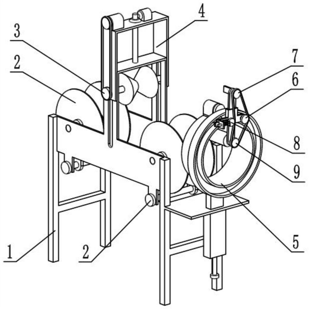
[0030] like Figure 1-11 As shown, a round steel polishing processing device includes a bracket 1, a guide wheel mechanism 2, a moving mechanism 3, an adjusting lifting mechanism 4, a polishing power frame 5, a rotating mechanism 6, a top tightening mechanism 7, a tensioning mechanism 8 and a polishing mechanism 9. There are two guide wheel mechanisms 2, and the two guide wheel mechanisms 2 are connected to the bracket 1, the adjustment lifting mechanism 4 is connected to the upper end of the bracket 1, and the moving mechanism 3 is connected to the adjustment On the lifting mechanism 4, the moving mechanism 3 is slidingly connected to the support 1, the moving mechanism 3 is located between the two guide wheel mechanisms 2, the polishing power frame 5 is connected to the right end of the support 1, and the rotating mechanism 6 is connected to the On the polishing power frame 5, the jacking mechanism 7 is connected to the rotating mechanism 6, the tensioning mechanism 8 is sli...
specific Embodiment approach 2
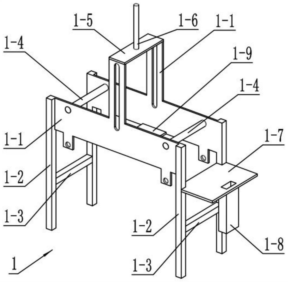
[0033] like Figure 1-11 As shown, the bracket 1 includes a side plate 1-1, a leg 1-2, a cross bar 1-3, a sliding shaft 1-4, an upper cross plate 1-5, a threaded rod 1-6, a mounting plate 1- 7. Fix the box pipe 1-8 and the connecting plate 1-9. There are two side plates 1-1. Both ends of the two side plates 1-1 are fixedly connected with supporting legs 1-2. A cross bar 1-3 is fixedly connected between the supporting leg 1-2 and the two supporting legs 1-2 positioned at the right end, and two sliding shafts 1-4 are provided, and the two sliding shafts 1-4 are rotatably connected on the two sides. Between the two side plates 1-1, the upper horizontal plate 1-5 is fixedly connected to the upper ends of the two side plates 1-1, the connecting plate 1-9 is fixedly connected to the lower ends of the two side plates 1-1, and the threaded rod 1- 6 is fixedly connected to the upper horizontal plate 1-5, the mounting plate 1-7 is fixedly connected to the two outriggers 1-2 at the righ...
specific Embodiment approach 3
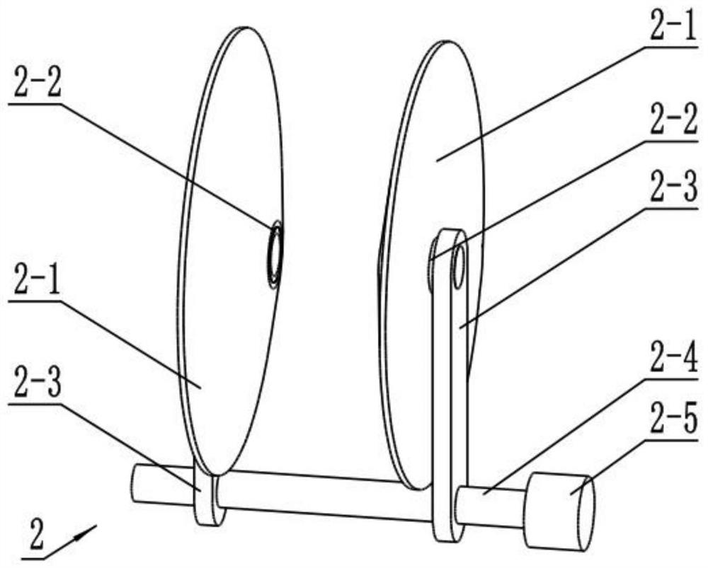
[0036] like Figure 1-11 As shown, the guide wheel mechanism 2 includes a conical side wheel 2-1, a wheel sleeve 2-2, a threaded plate 2-3, a double threaded rod 2-4 and a guide wheel adjustment motor 2-5, and the conical side wheel 2-1 is provided with two, the two conical side wheels 2-1 are both rotatably connected to the wheel sleeve 2-2, the two conical side wheels 2-1 are oppositely arranged, and the two wheel sleeves 2-2 are fixed Connected on the threaded plate 2-3, the two threaded plates 2-3 are threadedly connected to the two ends of the double threaded rod 2-4, the thread direction at the two ends of the double threaded rod 2-4 is opposite, the double threaded rod 2-4 and The output shaft of the guide wheel adjustment motor 2-5 is fixedly connected, and the guide wheel mechanism 2 is provided with two, and the two double-threaded rods 2-4 are all rotatably connected on the two side plates 1-1, and two groups of wheel sleeves 2-2 Slidingly connected to the two slid...
PUM
 Abstract
Description
Claims
Application Information
 - R&D
- Intellectual Property
- Life Sciences
- Materials
- Tech Scout
- Unparalleled Data Quality
- Higher Quality Content
- 60% Fewer Hallucinations
Browse by: Latest US Patents, China's latest patents, Technical Efficacy Thesaurus, Application Domain, Technology Topic, Popular Technical Reports.
© 2025 PatSnap. All rights reserved.Legal|Privacy policy|Modern Slavery Act Transparency Statement|Sitemap|About US| Contact US: help@patsnap.com


