Movable sucker device for mold

A suction cup and mold technology, applied in the coating and other directions, can solve the problems of poor reliability of the manipulator and positioning parts, inability to place the hardware in place, reducing the service life of the mold, etc. Risk, effect of avoiding interference

Active Publication Date: 2017-11-03
东莞华誉精密技术有限公司
View PDF4 Cites 0 Cited by
  • Summary
  • Abstract
  • Description
  • Claims
  • Application Information

AI Technical Summary

Problems solved by technology

[0004] In the prior art, the suction cup for absorbing the hardware is a fixed suction cup, so it is necessary to put the hardware in place before the suction cup can firmly adsorb the hardware on the mold, but in actual production, it is often due to various equipment or control processes. Factors cause the manipulator to fail to place the hardware in place, so that when the suction cup moves, the suction of the suction cup fails due to the non-vacuum between the mold and the hardware, which leads to the inability of the hardware to be placed on the mold. During the mold clamping process, it will cause film pressure, which will damage the mold and reduce the service life of the mold
In addition, since the manipulator needs to send the hardware to the molding surface close to the mold, the fixed suction cup can absorb the hardware, so the manipulator must go deep into multiple positioning parts, which will often cause friction between the manipulator and the positioning parts. Interference and collision phenomena, thereby deteriorating the reliability of the manipulator and positioning parts

Method used


Image

  • Movable sucker device for mold
  • Movable sucker device for mold
  • Movable sucker device for mold

Examples


Embodiment Construction

[0034] The present invention is further described in conjunction with the following examples.

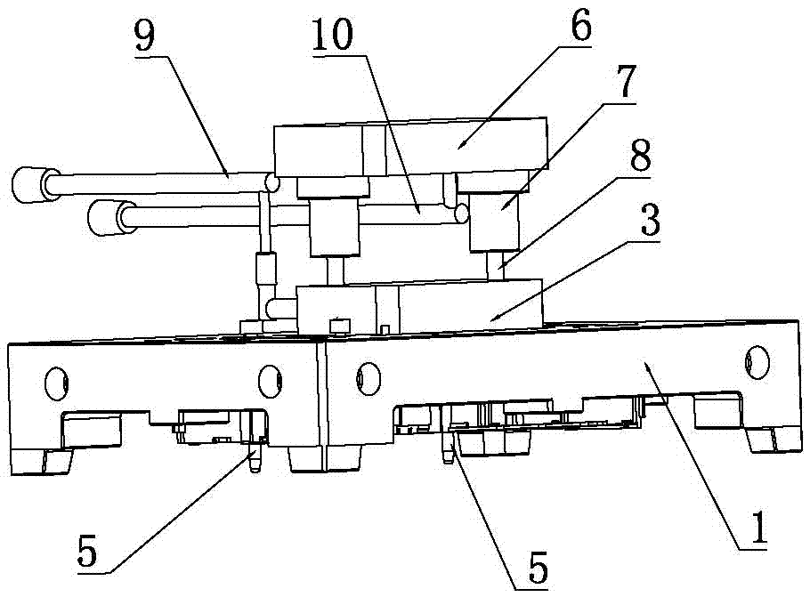
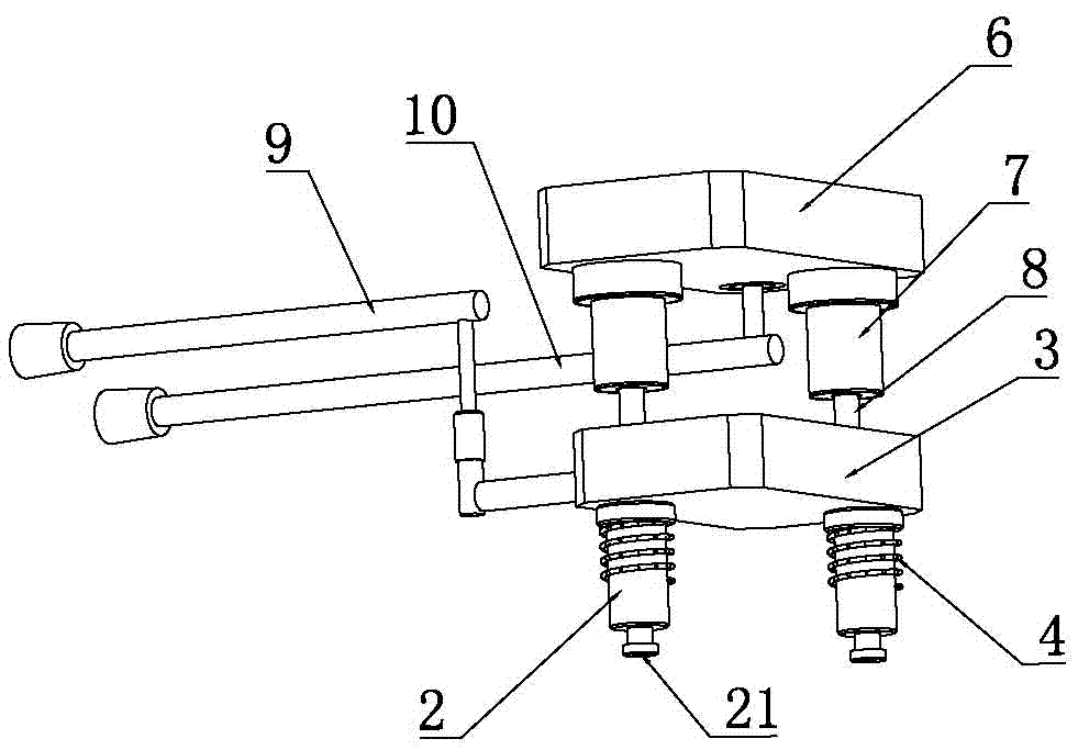
[0035] A specific embodiment of a movable sucker device for a mold of the present invention, as figure 1 and figure 2 As shown, it includes suction cup 2, positioning pin 5 and ejection assembly. The suction cup 2 and positioning pin 5 are set on the mold 1. The suction cup 2 can slide up and down relative to the mold 1. The ejection assembly (6, 7, 8) can push the suction cup 2 downward movement, and then push the suction end 21 of the suction cup 2 out of the molding surface of the mold 1 .

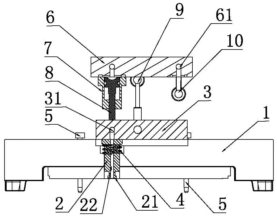
[0036] like figure 2 and image 3 As shown, the mold 1 is also provided with a suction plate 3 that can slide up and down relative to the mold 1, the suction cup 2 is fixed on the bottom of the suction plate 3, and the suction pipe 31 in the suction plate 3 communicates with the suction pipe 22 of the suction cup 2 and the first air supply source pipe 9 , the ejector assembly pushes the...


PUM


Abstract

The invention discloses a movable sucker for a die. The movable sucker structurally comprises a sucker, a positioning part and an ejecting assembly. The ejecting assembly can eject the adsorption end of the sucker out of a forming face of the die. In the process that a mechanical arm conveys hardware to be injected to the adsorption end of the sucker, the hardware to be injected can be primarily positioned through the positioning part, the sucker acts to adsorb the hardware to be injected to the sucker, and then the sucker retracts and resets; in the reset process, the hardware to be injected slightly moves relative to the sucker under limiting of the positioning part, so that the hardware to be injected is accurately positioned, the hardware to be injected is placed in place, and the risk of film pressing is effectively lowered; and in addition, due to the fact that the adsorption end of the sucker stretches out of the forming face of the die, when the mechanical arm conveys the hardware to be injected to the sucker, the mechanical arm does not need to make contact with the forming face of the die so that the mechanical arm can be prevented from damaging the forming face of the die, and meanwhile the space cross depth of the mechanical arm and the positioning part is effectively reduced so that the interference between the mechanical arm and the positioning part can be effectively avoided.

Description

technical field [0001] The invention relates to the technical field of mold fittings, in particular to a movable suction cup device for a mold. Background technique [0002] In the product injection molding production process, it is often necessary to place steel sheets or other hardware parts into the injection mold to form an in-mold injection molding process, and then insert the hardware parts into the product to enhance the structural strength of the product or increase the functional characteristics of the product. [0003] In the in-mold injection molding process, in order to improve production efficiency, a manipulator is generally used to place the hardware on the mold, and at the same time guide and position the hardware through the positioning piece. After the hardware is placed on the mold, the suction cup starts to suck Pneumatic action, and then the hardware is firmly adsorbed on the mold, so that the mold can prevent the hardware from loosening or falling durin...

Claims


Application Information

Patent Timeline
Patent Type & Authority Patents(China)
IPC IPC(8): B29C45/14B29C33/18
CPCB29C45/14065B29C2045/14155
Inventor 何智安
Owner 东莞华誉精密技术有限公司
Why Eureka
Try Eureka