Magnetic filling device

A filling device and magnetic technology, applied in the valve device, valve operation/release device, packaging and other directions, can solve the problems of not easy to be found, hidden dangers in safety and health, complicated replacement steps, etc. and the effect of the valve opening operation

Active Publication Date: 2016-01-20
JIANGSU NEWAMSTAR PACKAGING MACHINERY
View PDF7 Cites 2 Cited by
  • Summary
  • Abstract
  • Description
  • Claims
  • Application Information

AI Technical Summary

Problems solved by technology

[0002]At present, most of the aseptic filling devices rely on the aseptic diaphragm valve to control its opening and closing, and the diaphragm of the aseptic diaphragm valve is a vulnerable part. The replacement steps are relatively complicated, and it is not easy to be found after it is damaged, so there are certain safety and health risks

Method used


Image

  • Magnetic filling device
  • Magnetic filling device
  • Magnetic filling device

Examples


Embodiment Construction

[0018] The technical solution of the present invention will be further described below in conjunction with the accompanying drawings.

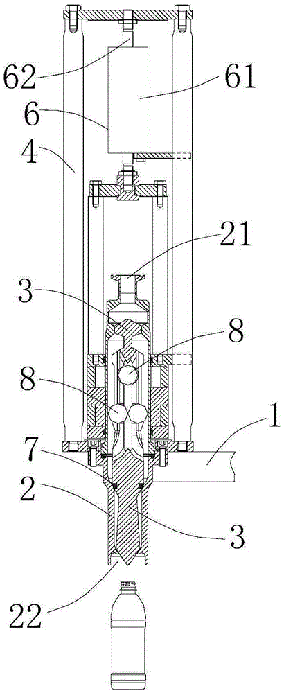
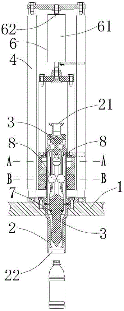
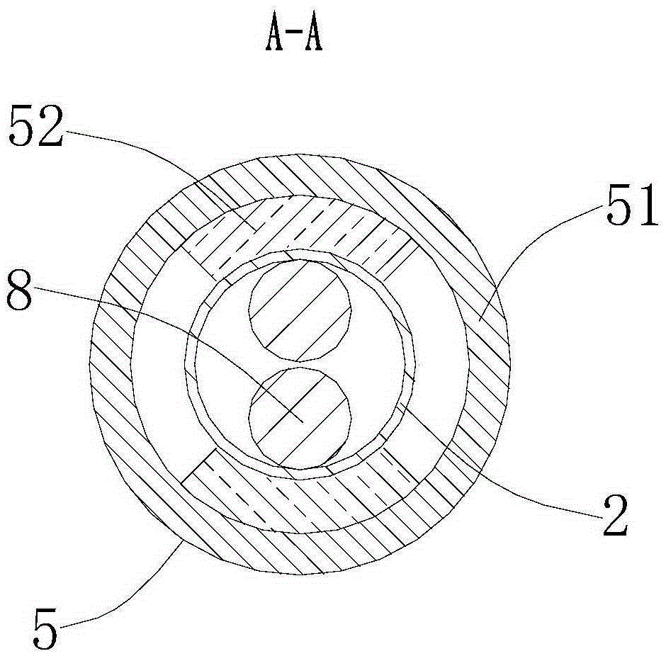
[0019] see Figure 1-4 Shown, above-mentioned a kind of magnetic force filling device is located on the frame 1. The device includes a valve body 2 arranged on the frame 1, a valve core 3 which is movable up and down in the valve body 2, a metal assembly fixedly connected with the valve core 3 in the valve body 2, The sealing ring 7 is arranged between the lower end of the valve body 2 and the lower end of the valve core 3 . The valve body 2 includes a liquid inlet 21 arranged at its upper end for inputting the filling liquid, and a liquid outlet 22 arranged at its lower end for outputting the filling liquid into the filling bottle. The device also includes a mounting base 4 fixed on the frame 1, a magnetic assembly 5 that is movable up and down in the mounting base 4, and a magnetic assembly 5 that is located in the mounting base 4 to drive...


PUM


Abstract

The invention discloses a magnetic filling device. The magnetic filling device is arranged on a rack and comprises a valve body arranged on the rack, a valve element arranged in the valve body and capable of moving up and down, and a metal component arranged in the valve body and fixedly connected to the valve element, wherein the valve body comprises a liquid inlet formed in the upper end and a liquid outlet formed in the lower end; the device also comprises a mounting base fixedly arranged on the rack, a magnetic component arranged in the mounting base and capable of moving up and down and a driving device arranged in the mounting base and used for driving the magnetic component to move up and down so as to attract the metal component to move up and down. Through the magnetic filling device, a metal ball is arranged on the valve element, the magnetic component capable of moving up and down is arranged at the exterior of the valve body, the magnetic component is driven by the driving device to move up and down so as to attract the metal ball to drive the valve element to move up and down, thereby implementing the operations of switching on and off the valve; the opening degree of the valve element can be conveniently adjusted to adjust the filling flow; and the magnetic filling device is substantially free of cleaning blind angle.

Description

technical field [0001] The invention relates to a magnetic filling device. Background technique [0002] At present, most of the aseptic filling devices rely on the aseptic diaphragm valve to control its valve opening and closing, but the diaphragm of the aseptic diaphragm valve is a vulnerable part, and the replacement steps are relatively complicated, and it is not easy to be found after it is damaged. safety and health hazards. Contents of the invention [0003] The purpose of the present invention is to provide a magnetic filling device, which basically has no hygienic dead angle and can conveniently adjust the filling flow. [0004] In order to achieve the above object, the technical scheme adopted in the present invention is: [0005] A magnetic filling device, set on a frame, the device includes a valve body set on the frame, a valve core set in the valve body movable up and down, a valve core set in the valve body A metal assembly fixedly connected with th...

Claims


Application Information

Patent Timeline
Patent Type & Authority Applications(China)
IPC IPC(8): F16K1/00F16K31/06F16K31/12B67C3/28
CPCB67C3/28F16K1/00F16K31/0655F16K31/08F16K31/12
Inventor 邹中全姚玲
Owner JIANGSU NEWAMSTAR PACKAGING MACHINERY
Why Eureka
Try Eureka